Flat Bed CNC Lathe

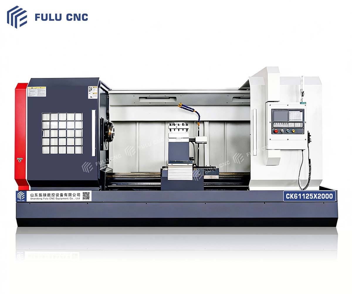
CK61125×2000 Flat Bed CNC Lathe

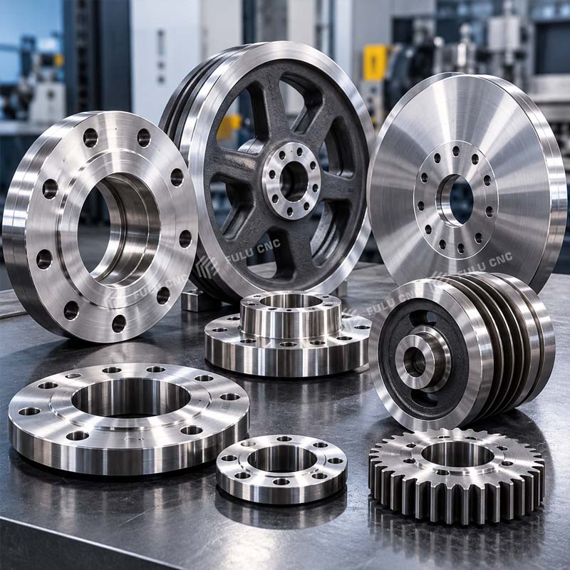
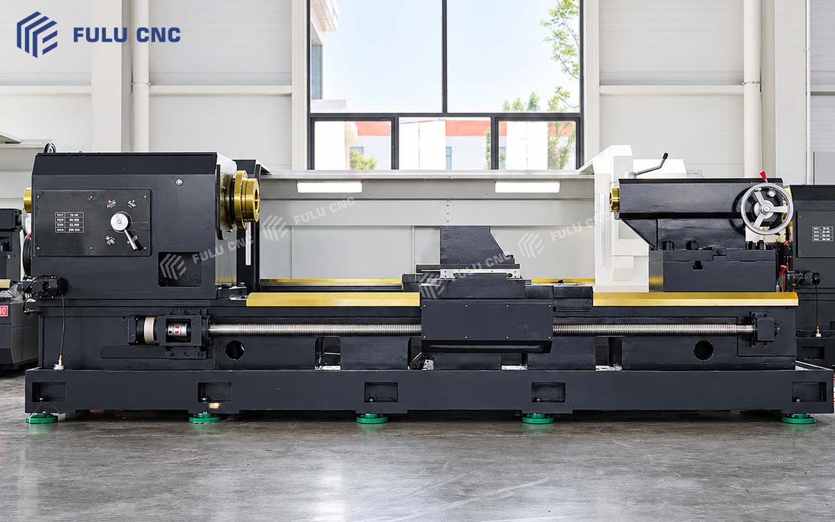
A two-axis CNC lathe for large-diameter shafts, flanges, discs, sleeves, and other rotational parts. Its reference configuration combines a 1,000 mm manual independent four-jaw chuck, a four-position electric turret, and a manual tailstock for general turning and thread cutting.

1,250 mm Swing Over Bed
2,000 mm Distance Between Centers
Approx. 1,850 mm Effective Machining Length
1,000 mm Manual Four-Jaw Chuck

Part and Model Fit

Is This Machine Right for Your Parts?

Use the part shape, maximum diameter, machining length, weight, material, operations, and production volume to judge initial fit. Final selection should be checked against the drawing and workholding plan.

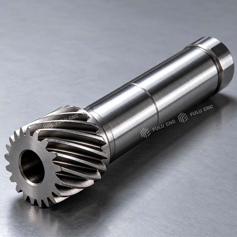
Large shaft, transmission shaft, and roller shaft workpieces

Large Shafts and Roller Shafts

For transmission shafts, roller shafts, and other long rotational parts used in heavy machinery, rolling equipment, and industrial production lines.

Flanges, wheels, and large disc parts

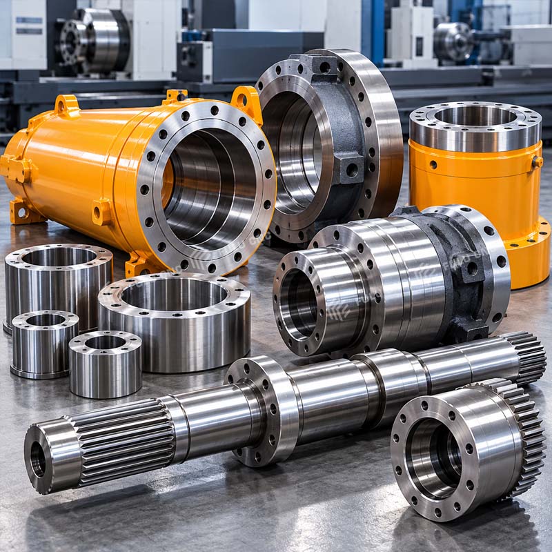
Flanges, Discs, Sleeves, and Cylinders

For large flanges, wheels, sleeves, cylinder barrels, bushings, and similar parts requiring outside, inside, face, taper, groove, or thread turning.
Large-diameter hydraulic and transmission parts

Hydraulic and Transmission Components

For couplings, hydraulic-cylinder components, and large connecting parts used in construction, agricultural, mining, and general industrial equipment.

Good Initial Fit

  • Rotational parts within the 1,250 mm swing over bed and 850 mm swing over carriage.
  • Required machining length does not exceed approximately 1,850 mm.
  • One-off, small-batch, or high-mix production using general turning and thread-cutting operations.
  • Workpieces that can be held by the 1,000 mm independent four-jaw chuck and supported by the tailstock when required.

Review Another Model or Support Plan

  • Large-diameter pipe must pass through the spindle or requires specialized pipe-end threads: review a pipe-threading CNC lathe.
  • Part diameter or machining length exceeds this machine's working range: review a larger-capacity or longer-bed model.
  • Slender or heavy long shafts may require a steady rest, auxiliary support, and an engineering review of workpiece weight and deflection.
  • Accuracy, workholding, or cycle requirements are critical: submit the drawing for configuration confirmation.

For a configuration review, provide the drawing, material, blank dimensions, critical tolerances, surface finish, batch size, destination, and electrical standard.

Submit Your Part Drawing

Machine Features

CK61125×2000 Design Advantages

Each feature below connects the machine configuration to its intended production role and the conditions that must be confirmed for a specific workpiece.
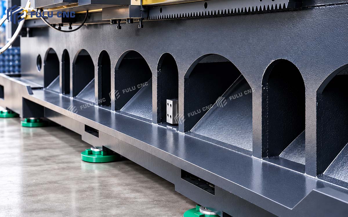
CK61125x2000 integral cast-iron flat bedAdd cast-iron bed image URL
01

Integral Cast-Iron Bed for a Stable Heavy-Turning Foundation

The CK61125×2000 uses an integral flat-bed structure and a high-quality cast-iron bed. Its fully enclosed design is intended for safe, straightforward operation. Cast iron provides vibration absorption and damping, while the wide rectangular guideways help distribute loads generated by the spindle, turret, and large workpieces.

This structure is suitable for large-diameter shafts, disc-and-sleeve parts, and heavy rotational components. With appropriate workholding and cutting parameters, it can reduce vibration and structural deformation during heavy cutting, providing a stable mechanical foundation for dimensional consistency, roundness, and surface quality.
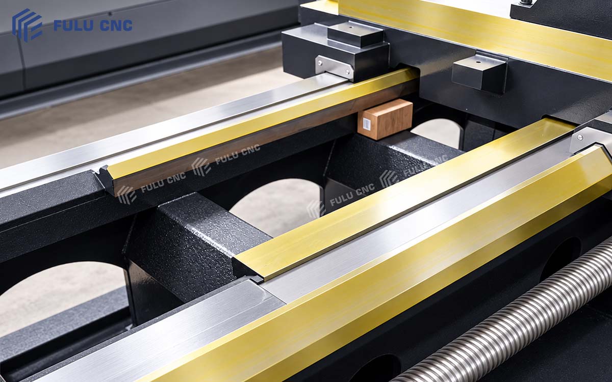
Rectangular hardened guideway structureAdd guideway image URL
02

Rectangular Hardened Guideways for Load Capacity and Wear Resistance

The machine uses rectangular hardened guideways with a relatively large contact area, suitable for radial and axial cutting loads generated while machining large workpieces.

The guideway surfaces receive medium-frequency induction hardening to increase surface hardness and wear resistance. Together with the automatic lubrication system, this continuously supplies lubricant to the guideways and ball screws, reducing friction and abnormal wear and helping maintain stable feed performance during long-term operation.
Long shaft supported between chuck and tailstockAdd long-shaft support image URL
03

Wide-Span Bed Design for Stable Long-Shaft Machining

The CK61125×2000 provides a 2,000 mm distance between centers and an effective machining length of approximately 1,850 mm, supporting the machining of large transmission shafts, roller shafts, cylinder barrels, and long sleeves.

The bed, spindle, turret, and tailstock form a stable support system. Supporting a long shaft with the tailstock can reduce workpiece movement and deflection under cutting forces. Slender shafts with a high length-to-diameter ratio may require a steady rest or auxiliary support.
Large-diameter workpiece turning at low spindle speedAdd low-speed turning image URL
04

Low-Speed Capability for Large-Diameter Machining

The spindle uses segmented variable-frequency speed control, with a reference speed range of 30-835 r/min. Lower spindle speeds suit the turning requirements of large-diameter workpieces, and the available speed ranges can be selected according to workpiece diameter, material, and machining stage.

This spindle configuration can support both rough turning of large workpieces and conventional finish turning. Specific heavy-cutting capability must be confirmed against main-motor power, the spindle torque curve, tooling, and cutting parameters.
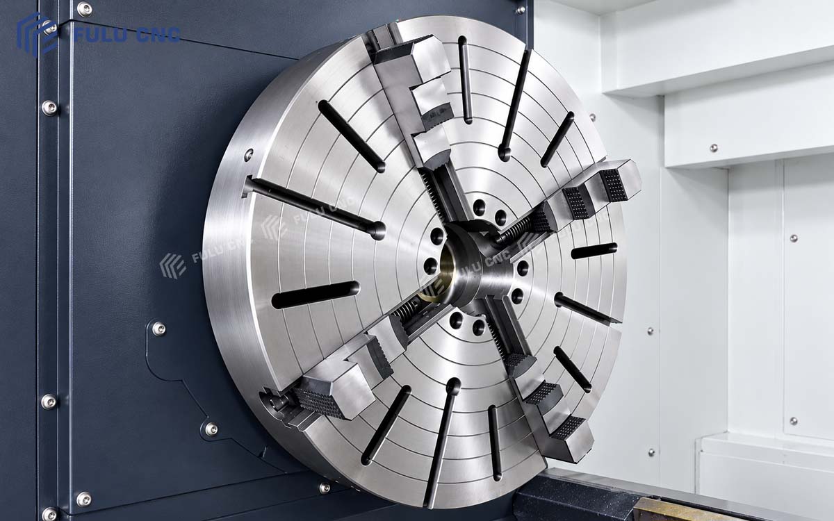
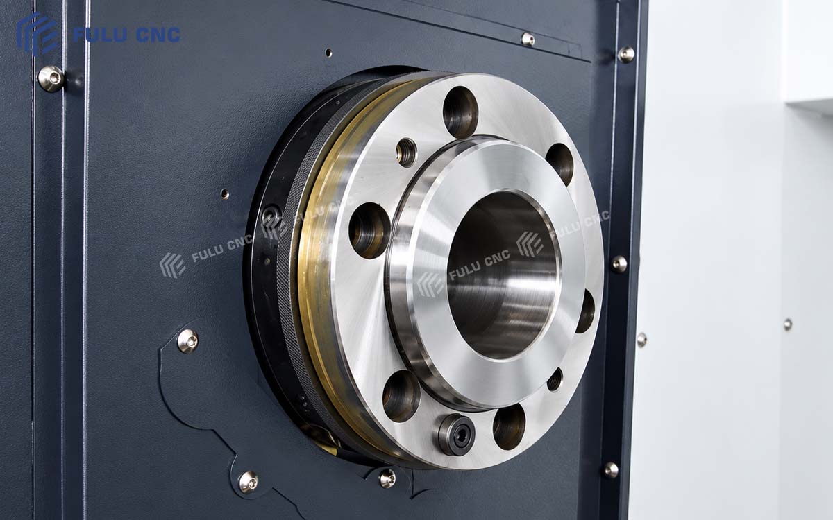
1000 mm manual independent four-jaw chuckAdd four-jaw chuck image URL
05

1,000 mm Four-Jaw Chuck for Large and Irregular Workpieces

The standard reference configuration includes a 1,000 mm manual independent four-jaw chuck. Each jaw can be adjusted independently, allowing centering and clamping of large round workpieces as well as castings, forgings, eccentric parts, and some irregular components.

Compared with a conventional self-centering three-jaw chuck, an independent four-jaw chuck offers more adjustment flexibility for controlling workpiece center position and clamping condition. The actual clamping range, workpiece weight, and maximum safe rotational speed must be confirmed for the specific workpiece.
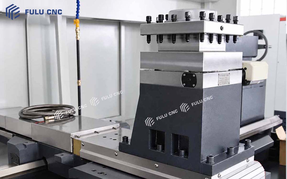
Four-position electric turretAdd electric turret image URL
06

Four-Position Electric Turret to Reduce Manual Tool Changes

The machine is equipped with a four-position electric turret that can hold tools for outside turning, boring, grooving, and threading. During machining, the CNC program indexes the turret automatically, reducing manual tool changes and repeated tool setting.

The four-position turret supports continuous multi-operation machining of outside diameters, faces, bores, tapers, grooves, and threads, helping improve efficiency for small-batch and high-mix production.
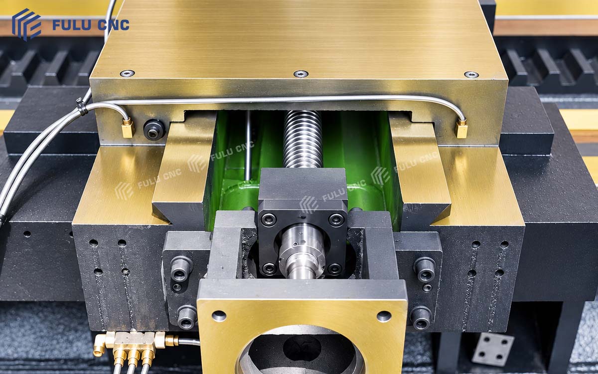
X and Z axis ball-screw feed systemAdd ball-screw feed image URL
07

Ball-Screw Feed for Motion Response and Positioning Consistency

The X and Z axes use ball-screw drives. Their relatively low friction helps improve feed response while reducing the crawling and transmission backlash associated with conventional sliding screws.

Combined with the CNC servo system, the drives provide stable radial and axial feeds for steps, tapers, arcs, and thread profiles. Actual positioning accuracy and repeatability must be based on the machine's factory inspection report and the technical agreement.
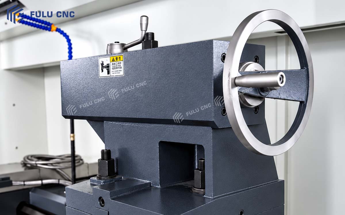
Manual tailstock supporting a long shaftAdd manual-tailstock image URL
08

Manual Tailstock for Long-Shaft and Deep-Hole Machining Support

The machine is equipped with a manual tailstock with a Φ100 mm quill and a 250 mm quill travel. For long shafts, the tailstock supports the workpiece from the opposite end to reduce movement and deflection during cutting.

The tailstock can also carry a drill, center drill, or reamer for center drilling, drilling, and reaming. For heavy workpieces, the tailstock and auxiliary-support arrangement must be confirmed according to workpiece weight, thrust, and machining method.

Automatic lubrication system for guideways and ball screwsAdd lubrication-system image URL
09

Automatic Lubrication System

The automatic lubrication unit supplies oil to the guideways, ball screws, and other moving components at preset intervals, reducing abnormal wear caused by delayed manual lubrication. Lubrication intervals, lubricant type, and maintenance requirements must follow the machine documentation supplied with the final configuration.

Machine Data

Complete Technical Specifications

Machining Capacity

ParameterUnitCK61125×2000
Maximum workpiece swing over bedmm1,250
Maximum workpiece swing over carriagemm850
Maximum workpiece length between centersmm2,000
Effective machining lengthmm1,850
Bed guideway widthmm600 / 755; confirm according to the final machine structure

Spindle and Workholding

ParameterUnitCK61125×2000
Spindle bore diametermmΦ105 / Φ130
Spindle nose-A2-11
Spindle speed rangesr/min30-84 / 53-150 / 125-350 / 300-835
Speed control-Segmented stepless variable-frequency control
Standard chuckmm1,000 mm manual four-jaw chuck
Main motor powerkW15 kW reference standard configuration; final value subject to the configuration list

Feed Axes

ParameterUnitCK61125×2000
Maximum X-axis travelmm620
Maximum Z-axis travelmm2,000
X-axis rapid traversem/min4
Z-axis rapid traversem/min6
Controlled axes-X / Z, two axes

Turret

ParameterUnitCK61125×2000
Turret type-Vertical four-position electric turret
Number of tool positionspcs4
Reference tool shank sectionmm40×40

Tailstock

ParameterUnitCK61125×2000
Tailstock type-Manual tailstock
Tailstock quill diametermmΦ100
Tailstock quill travelmm250
Tailstock quill taper-Morse No. 6; final value subject to the technical agreement

Dimensions and Installation

ParameterUnitCK61125×2000
Reference overall dimensions (L×W×H)mmApprox. 3,900×2,000×2,000
Machine weightkgConfirm according to the final configuration
Power supply-Configured according to destination voltage and frequency
Foundation requirements-Subject to the final foundation drawing

Standard Reference Configuration

Configuration ItemStatusDescription
GSK980TB3i CNC systemStandard reference configurationBus-type absolute-position system
Main motorStandard reference configurationReference power: 15 kW
1,000 mm four-jaw chuckStandardManual independent four-jaw type
Four-position electric turretStandardProgram-controlled automatic indexing
Manual tailstockStandardSupports long shafts or carries tailstock tooling
Automatic lubrication unitStandardSupplies oil to guideways and ball screws at timed intervals
Handheld electronic handwheelStandard reference configurationUsed for tool setting and manual adjustment
Coolant systemAccording to final configurationParameters and capacity require confirmation

Optional and Engineered Configuration

Configuration ItemStatusApplicable Situation
FANUC CNC systemOptionalSpecified control platform or factory programming standard
Siemens CNC systemOptionalIntegration with an existing control platform
Other approved CNC systemTo confirmServo, electrical, and functional compatibility must be checked
Six- or eight-position electric turretOptionalMore operations or additional tools are required
Hydraulic tailstockOptionalReduced manual clamping operation is required
Hydraulic chuck and hydraulic unitEngineered optionMust be designed for the workpiece, spindle interface, and safe rotational speed
Special jaws or workholding fixtureCustom engineeringIrregular, thin-wall, or eccentric workpieces
Steady rest or auxiliary supportTo confirmSlender shafts and heavy long-shaft machining
Automatic loading and unloading interfaceCustom engineeringBatch production or automated machining projects

Optional items may affect machine price, delivery time, overall dimensions, working envelope, and electrical configuration. Each item must be confirmed separately in the technical agreement.

Model Fit

Quick Selection Guide

Use the workpiece diameter, machining length, weight, material, thread requirements, and machining allowance to determine whether this model fits the job.

Customer RequirementRecommended DirectionReason for SelectionNext Step
Large shafts, flanges, disc-and-sleeve parts, and roller shaftsCK61125×2000The 1,250 mm swing over bed suits general turning of large-diameter rotational parts.Provide workpiece diameter and drawing.
Required machining length does not exceed 1,850 mmCK61125×2000The distance between centers is 2,000 mm, with an effective machining length of approximately 1,850 mm.Confirm the actual machining length.
Large-diameter long pipe or pipe-end thread machiningPipe-threading CNC latheA large spindle bore and front-and-rear double-chuck arrangement better support pipe pass-through and stable clamping.Provide pipe outside diameter and length.
Workpiece exceeds this machine's machining rangeLarger-capacity or longer-bed modelA larger swing diameter, load capacity, or machining length is required.Request a model comparison.
Suitable model cannot be determinedSubmit the workpiece drawingSelection depends on diameter, length, weight, material, thread, and machining allowance.Submit the drawing and machining requirements.

For an engineering review, provide the drawing, material, blank dimensions, critical tolerances, surface finish, batch size, destination, and electrical standard.

Submit Your Part Drawing

Selection Comparison

Flat Bed CNC Lathe or Pipe-Threading CNC Lathe?

A general flat bed CNC lathe and a pipe-threading CNC lathe both use a horizontal-bed structure, but they are designed around different workpieces and clamping methods.

The CK61125×2000 focuses on general turning of large-diameter shafts, disc-and-sleeve parts, and heavy rotational components. A pipe-threading CNC lathe focuses on passing long pipe through the spindle, clamping it at the front and rear, and machining pipe-end threads. Selection should be based on workpiece form, pipe outside diameter, machining length, and thread requirements rather than swing over bed alone.

Comparison ItemCK61125×2000 Flat Bed CNC LathePipe-Threading Flat Bed CNC Lathe
Primary workpiecesLarge shafts, flanges, wheels, sleeves, roller shafts, and heavy rotational partsOil tubing, casing, drill pipe, conveying pipe, and other long pipe components
Core purposeGeneral turning of outside and inside diameters, faces, tapers, grooves, and threadsInternal and external pipe-end threads, tapered pipe threads, and long-pipe turning
Spindle boreΦ105 / Φ130 mm; confirm according to configurationUsually a larger spindle bore; select 200 / 300 / 400 mm according to the model
Workholding1,000 mm four-jaw chuck used with a tailstockUsually front and rear spindle chucks for clamping long pipe
Workpiece through spindleOnly bar or pipe with a diameter smaller than the spindle bore can pass throughDesigned for large-diameter pipe to pass through the spindle
Long-workpiece supportTailstock, steady rest, or auxiliary supportFront and rear chucks combined with a pipe support stand
Thread capabilitySuitable for conventional metric, imperial, and CNC-program-supported turned threadsBetter suited to large-pitch, tapered, and oil-country tubular threads
Typical production modeOne-off, small-batch, and high-mix general machiningSpecialized or batch machining of pipe and pipe-end threads
Main advantageWide machining range and adaptability to large-diameter disc and shaft partsLarge spindle bore, long-pipe pass-through, and stronger pipe-clamping capability

Quality Documentation

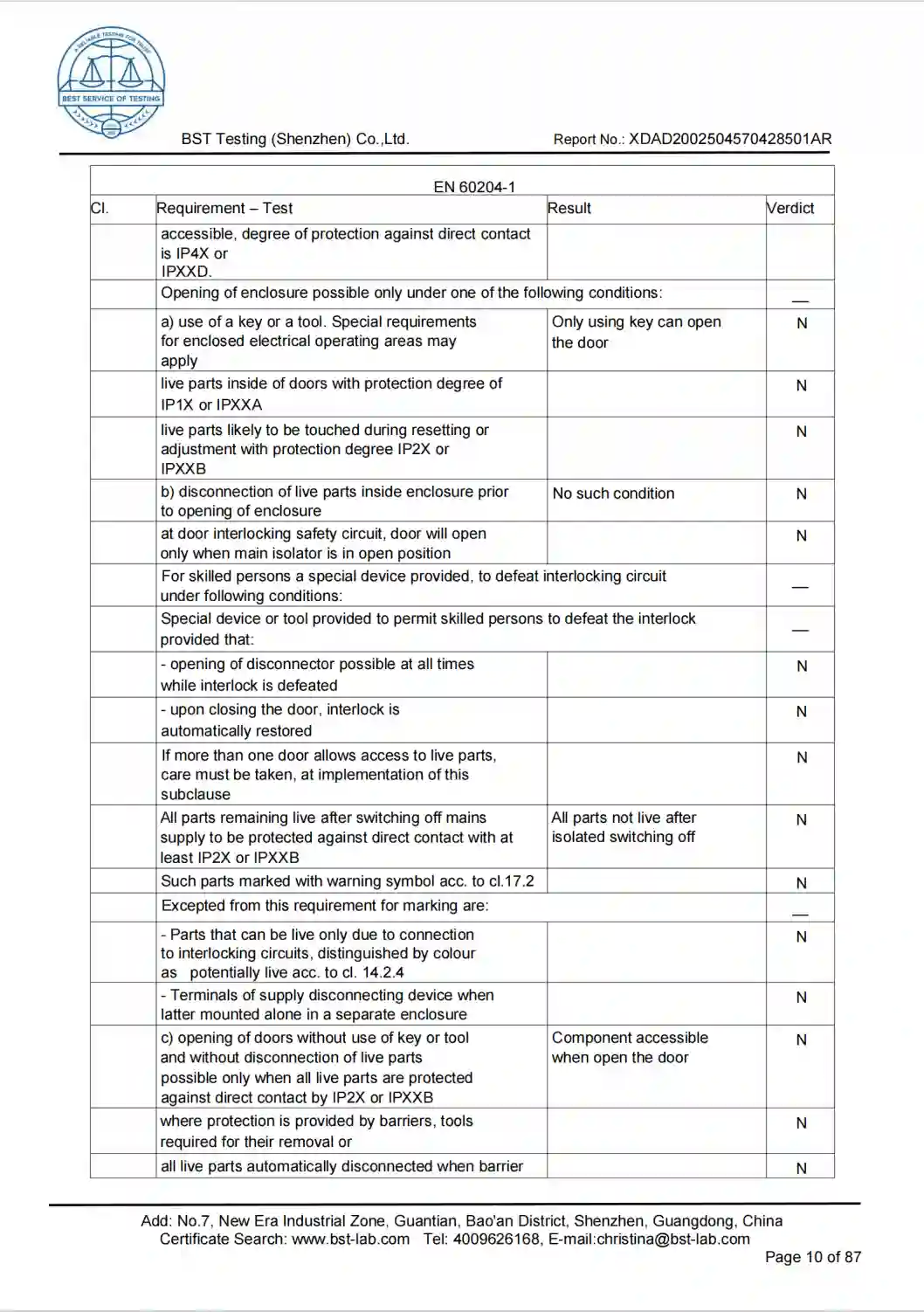
Company Certificates

Common Questions

CK61125×2000 FAQ

What is the maximum turning diameter of the CK61125×2000?

The maximum workpiece swing over bed is 1,250 mm, and the maximum workpiece swing over carriage is 850 mm. The actual turnable diameter must be confirmed according to turret position, chuck, tooling, and workholding. Swing over bed must not be treated as the maximum turning diameter under every operating condition.

Can the full length of a 2,000 mm workpiece be machined?

The maximum workpiece length between centers is 2,000 mm, but the reference effective machining length is 1,850 mm. Chuck clamping length, tailstock center, tool clearance, and workpiece-end geometry must also be considered.

Is this machine suitable for slender shafts?

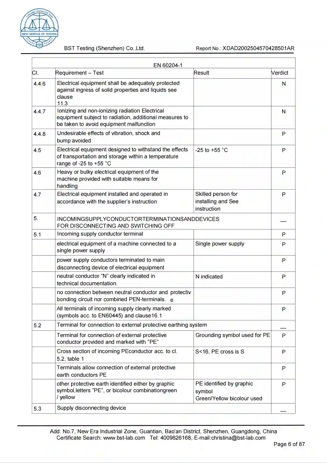
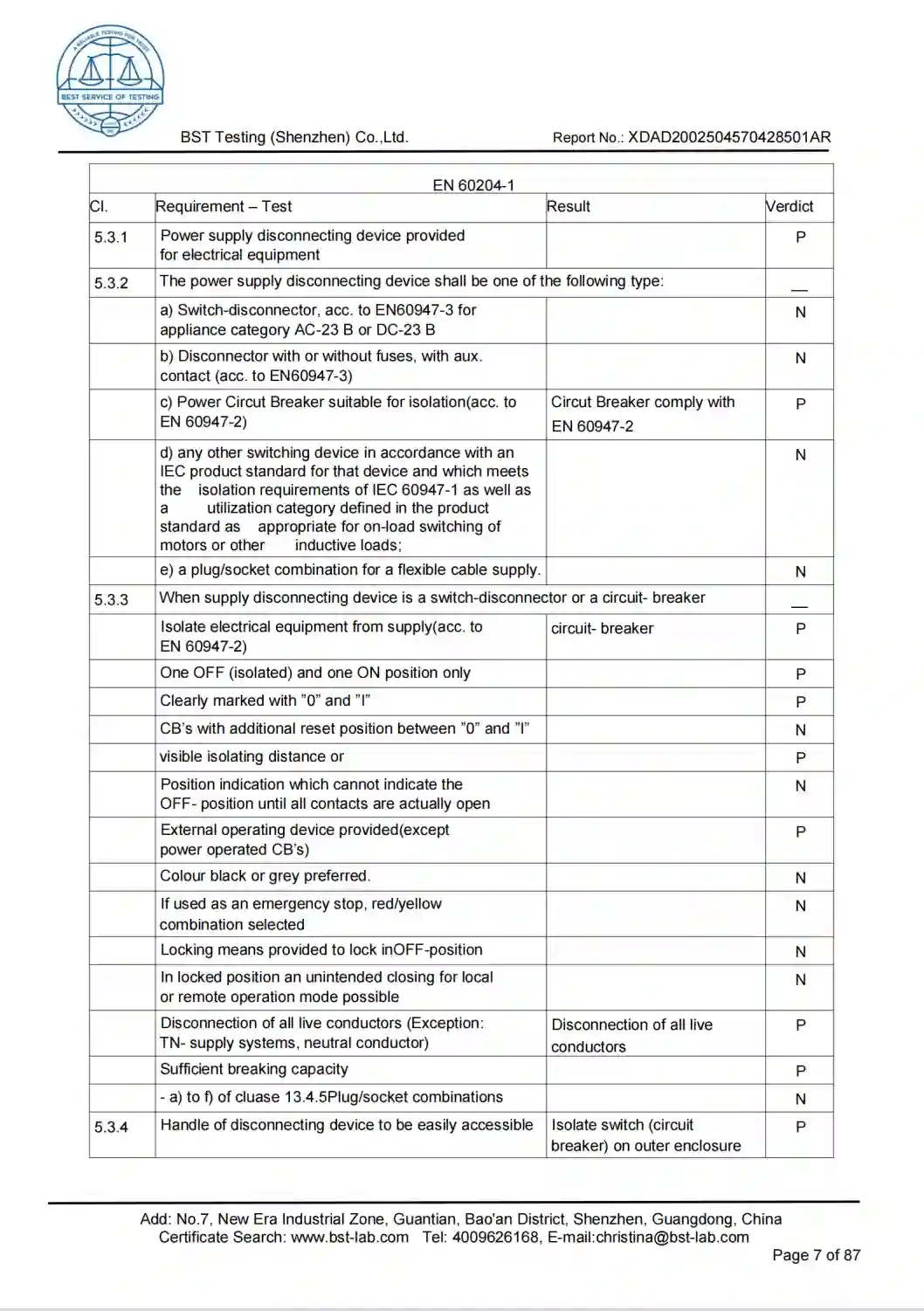
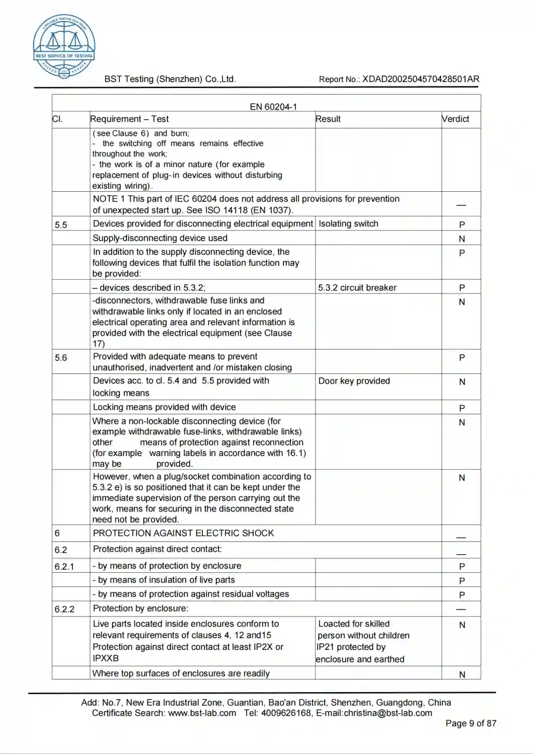
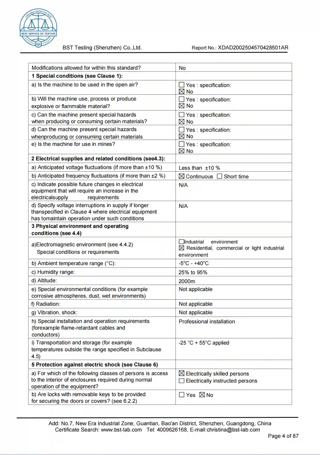
The machine includes a tailstock for supporting long shafts. For slender shafts with a high length-to-diameter ratio, the steady rest, follower rest, cutting parameters, and workpiece-deformation control plan must also be evaluated.

Is the spindle bore Φ105 mm or Φ130 mm?

The reference information lists both Φ105 mm and Φ130 mm. The value must be confirmed according to the final spindle configuration. When requesting a quotation, state the raw-material diameter and whether bar stock must pass through the spindle.

Can a FANUC or Siemens CNC system be selected?

A FANUC or Siemens CNC system can be evaluated according to project requirements. A control-system change may affect the servo system, electrical configuration, functional interfaces, price, and delivery time.

Can the machine be configured with a hydraulic chuck and hydraulic tailstock?

They can be evaluated as engineered options. A hydraulic chuck must match the spindle interface, workpiece dimensions, clamping force, and maximum safe rotational speed. A hydraulic tailstock requires confirmation of the clamping method, pressure control, and operating requirements.

What machining accuracy can the machine achieve?

Machining accuracy must be evaluated according to workpiece material, dimensions, workholding, tooling, and acceptance conditions. Provide the workpiece drawing and critical tolerances so the engineering team can confirm the process plan and acceptance standard.

What information is required for a quotation?

Provide the workpiece drawing, material, blank dimensions, maximum machining diameter, machining length, critical tolerances, surface roughness, batch quantity, CNC-system preference, destination country, and local voltage and frequency.