
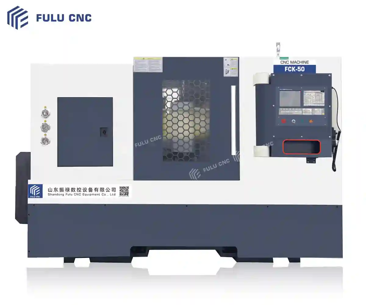
Slant Bed CNC Lathe
FCK50 Slant Bed CNC Lathe
Turn shafts, discs, sleeves, flanges, and threaded components with 550 mm swing over bed, 440 mm maximum cutting diameter, and 500 mm maximum cutting length. Select a 10, 12, or 15 inch hydraulic chuck to fit the workpiece.
Part and Model Fit
Is the FCK50 Right for Your Parts?
Assess part diameter, machining length, material, operations, volume, and workholding.
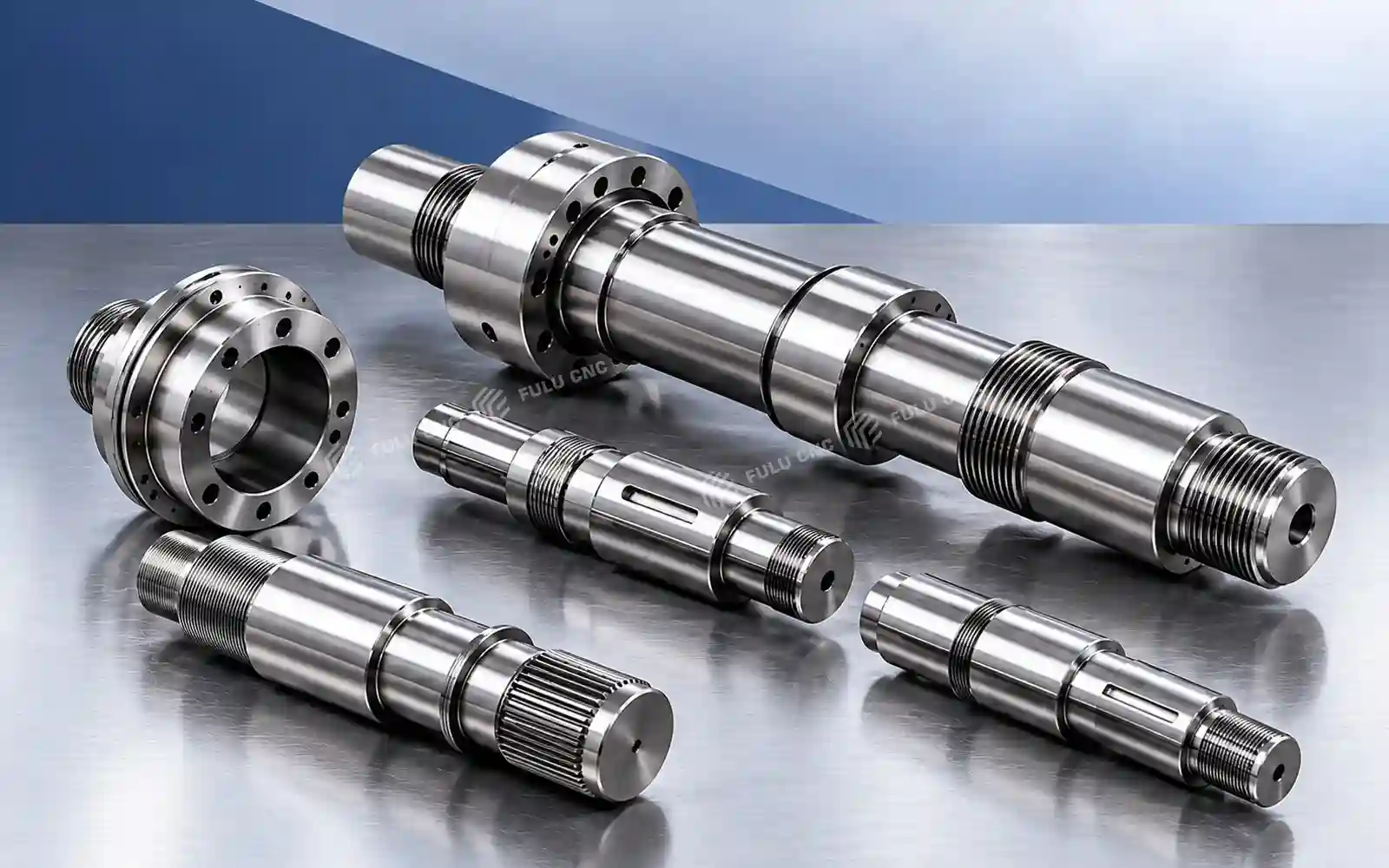
Shafts and Stepped Shafts
Motor shafts, drive shafts, pins, and rotational parts with shoulders, grooves, or threads.
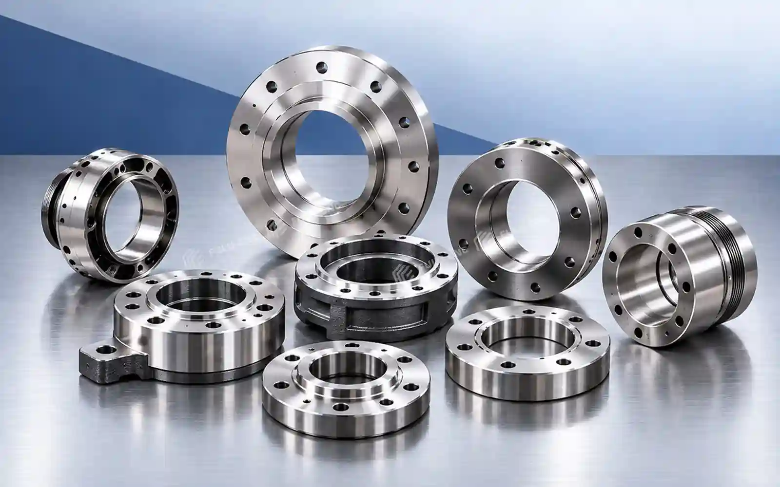
Discs, Flanges, and Rings
Faces, outer profiles, bores, and grooves on compact disc and flange components.
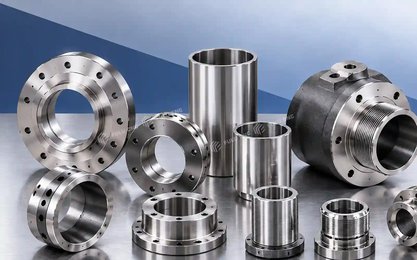
Sleeves, Bushings, and Threaded Parts
Internal and external turning on sleeves, bushings, nuts, and short pipe components.
Good Initial Fit
Parts within 440 mm cutting diameter and 500 mm cutting length, with suitable chuck and tailstock support.
Review the Workpiece
Thin walls, slender shafts, critical tolerances, or bar feed require a workholding and process review.
Machine Features
FCK50 Design Advantages
Each feature connects a verified FCK50 configuration to its machining role, production benefit, and the conditions that should be checked against the workpiece.
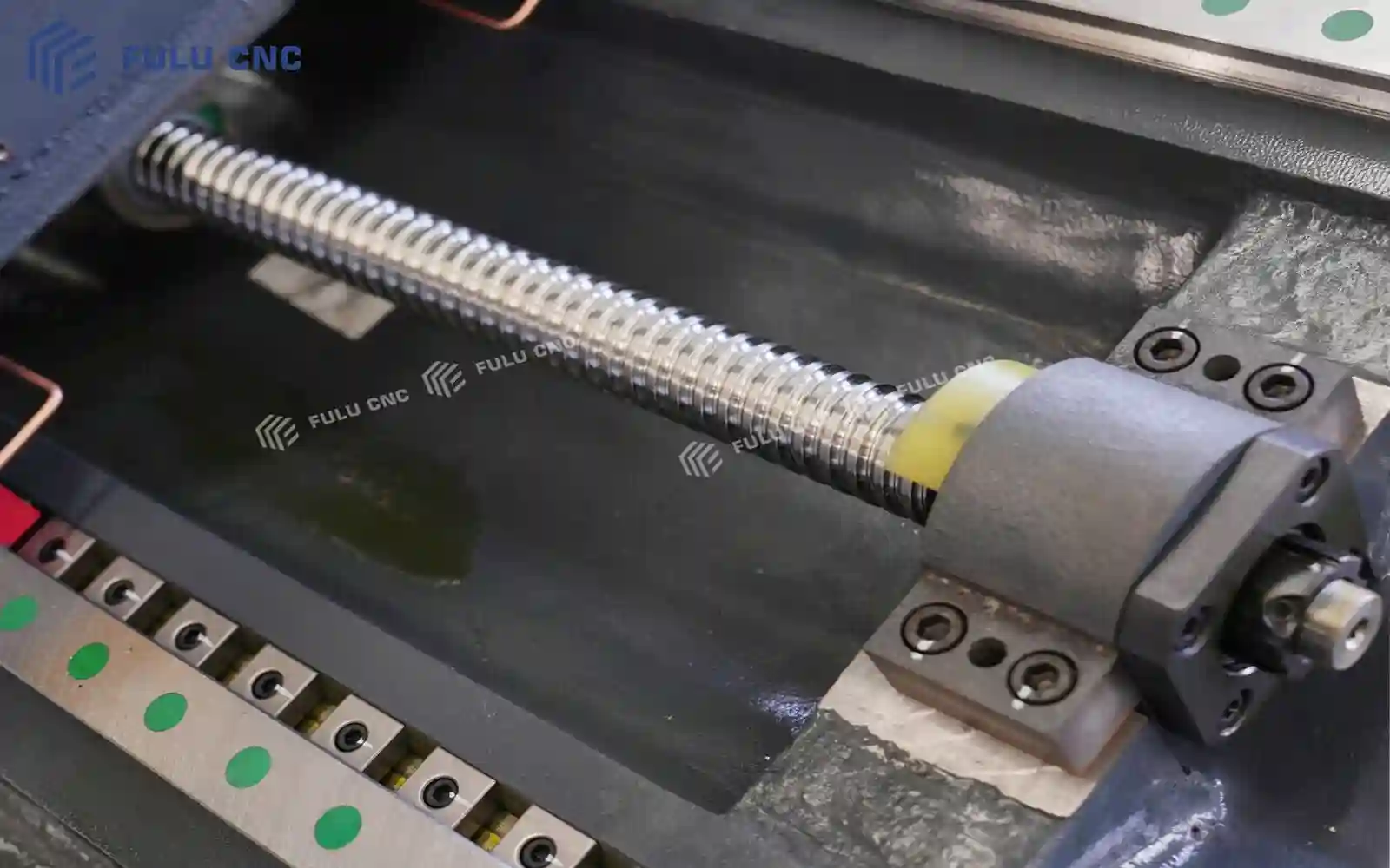
Linear Guideways and Slant-Bed Layout for Responsive Turning
The FCK configuration uses linear guideways as standard. Their rolling contact supports low-friction axis movement, while the slant-bed arrangement brings the tool and work area into an accessible layout and encourages chips to fall away from the cutting zone.
For shaft, sleeve, disc, and threaded-part work, this arrangement supports responsive positioning and convenient access for setup, tool checks, and chip removal. Actual cutting stability depends on workpiece overhang, chucking, tool reach, material, and cutting parameters; choose the TCK hardened-guideway structure when guideway load capacity for heavier cuts is the priority.
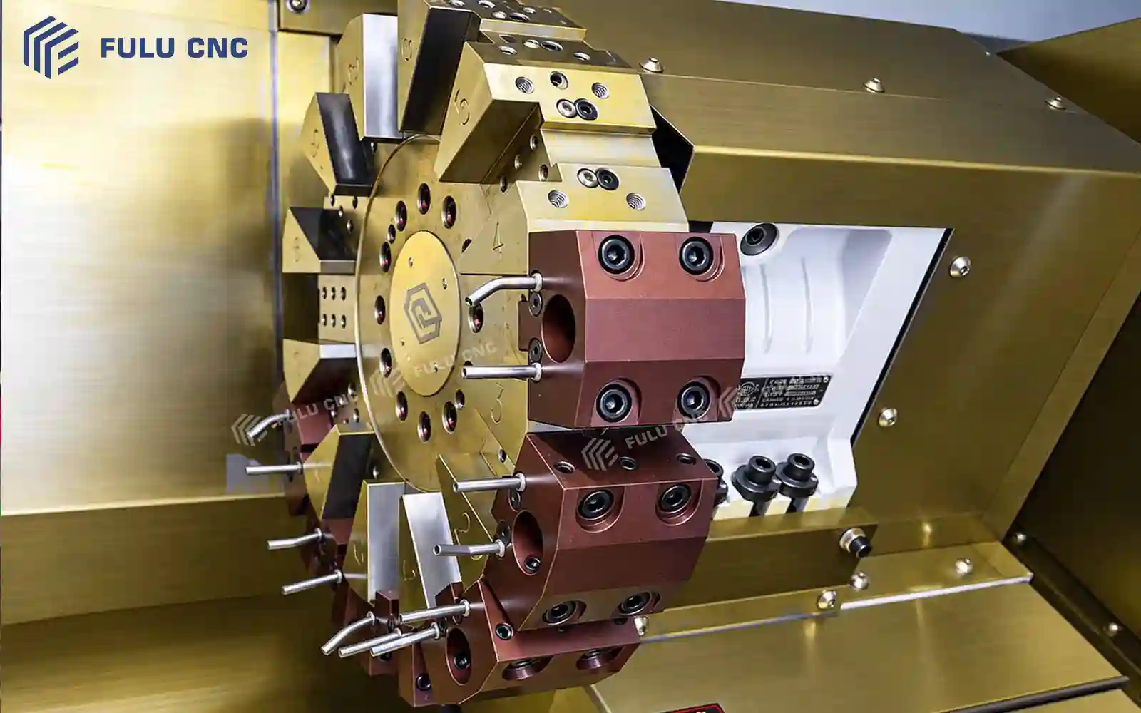
Optional 12-Station Servo-Hydraulic Turret for Fewer Manual Tool Changes
The optional 12-station servo-hydraulic turret indexes between mounted tools for operations such as external turning, boring, grooving, and threading. The listed tool shank section is 25 × 25 mm, with a 32 mm boring-bar mounting diameter.
Mounting multiple tools in one turret can reduce manual tool changes and repeated setup between turning operations, helping keep a multi-step part in one chucking where tool access permits. The turret is optional, not standard; confirm station layout, tool interference, boring-bar reach, indexing functions, and controller compatibility against the process plan.
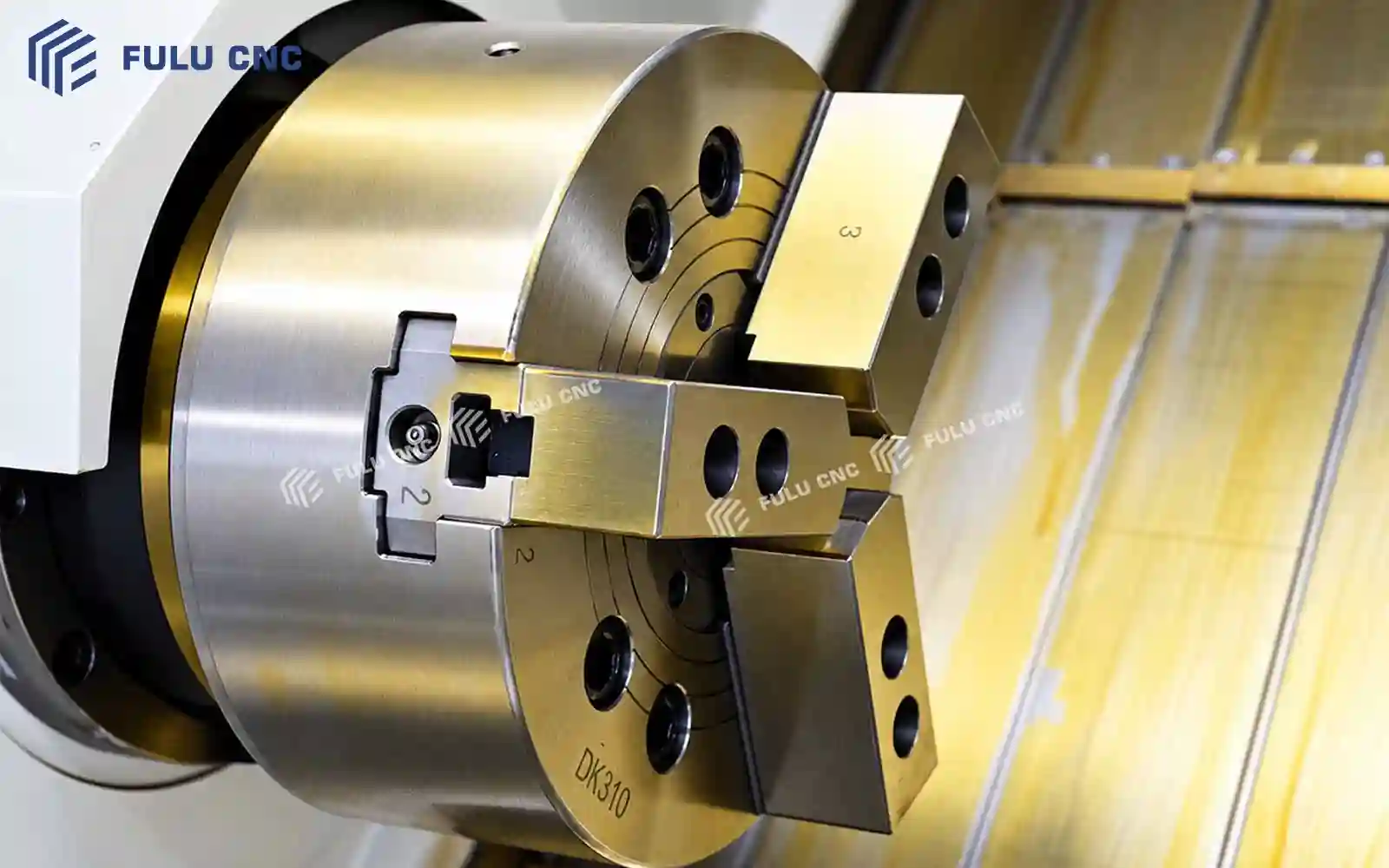
Three Hydraulic Chuck Sizes to Match the Workpiece
FCK50 can be configured with a 10, 12, or 15 inch hydraulic three-jaw chuck. Selecting the chuck size around the part diameter and gripping length helps establish suitable jaw engagement without choosing a larger workholding unit than the job requires.
Correctly matched workholding supports repeatable loading and secure clamping for production turning of round parts such as shafts, sleeves, and flanges. Chuck size alone does not determine safe capacity: verify spindle interface, jaw type and reach, workpiece mass, clamping force, and permitted rotational speed for the actual part.
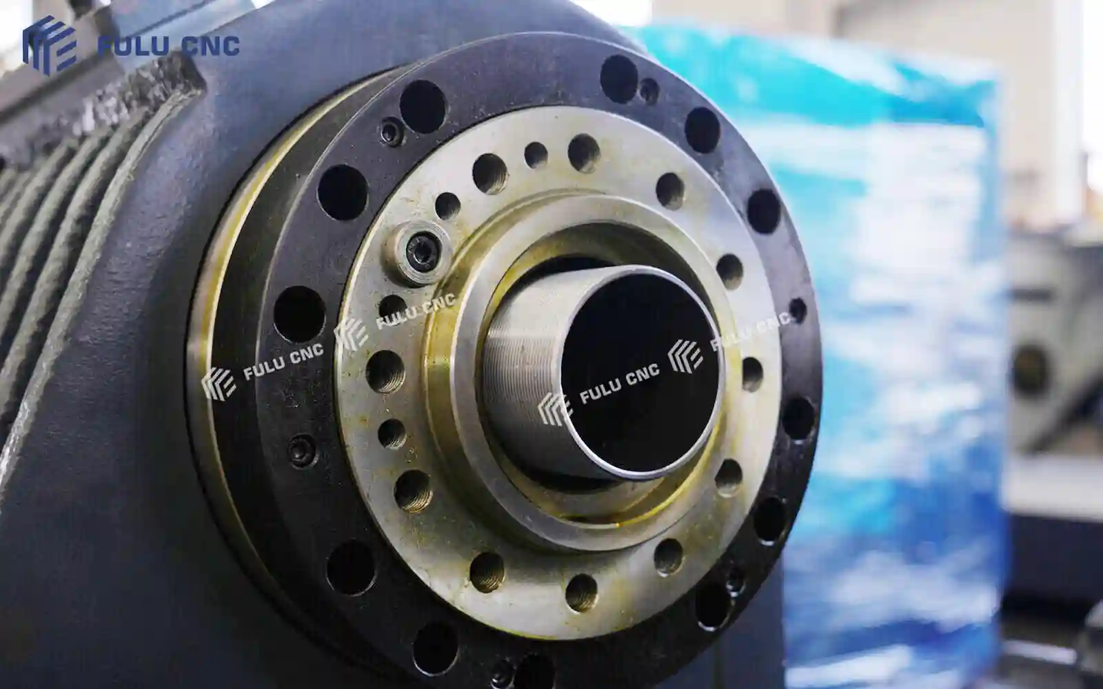
48 N·m Maximum Spindle Torque for Turning Loads
The FCK50 spindle is specified with a maximum torque of 48 N·m. Torque is the spindle's turning force and is a practical reference when evaluating the load created by workpiece diameter, material, tool geometry, and depth of cut.
This value helps the production team assess whether a proposed turning operation is within the machine's intended process range and compare cutting conditions during application review. Maximum torque is not a guarantee of the same force at every spindle speed; confirm the torque-speed curve, duty condition, tooling, and cutting data for the selected spindle configuration.
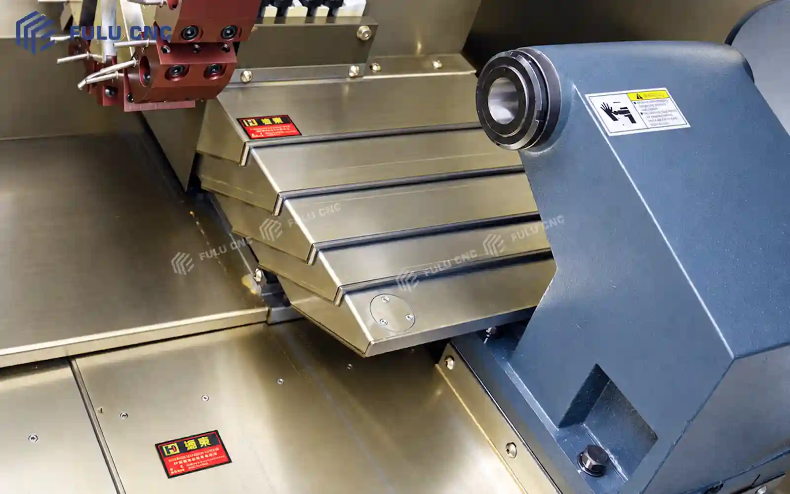
Standard Manual Tailstock for Workpiece Support
The standard configuration uses a manual tailstock with 500 mm travel and an MT5 center taper. It can support the free end of a suitable shaft or carry compatible center-drilling and drilling tools, subject to the workpiece and tool setup.
Supporting a long or slender workpiece from the tailstock can reduce unsupported overhang and help control deflection under cutting force, improving the conditions for stable turning. The operator positions and clamps the standard tailstock manually; a hydraulic tailstock is available as an option when the production process calls for powered positioning or clamping. Confirm center height, support force, travel, and any auxiliary support needs for the part.
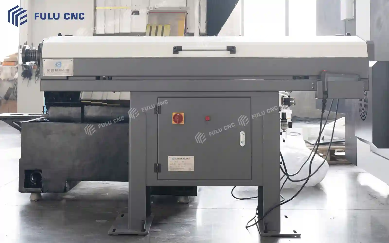
Configurable Automation for Repeat Production
Depending on the final FCK50 setup, automation can include a servo bar feeder, part collector, chain chip conveyor, or an automatic loading interface. These are configuration choices for an application, not functions assumed to be included on every machine.
When matched to part size and production flow, bar feeding can reduce manual stock loading, a part collector can receive completed components, and chip conveying can move chips away from the work area. The loading interface can support integration planning with external equipment. Confirm part range, cycle sequence, machine signals, guarding, floor layout, and integration responsibility before specifying an automated cell.
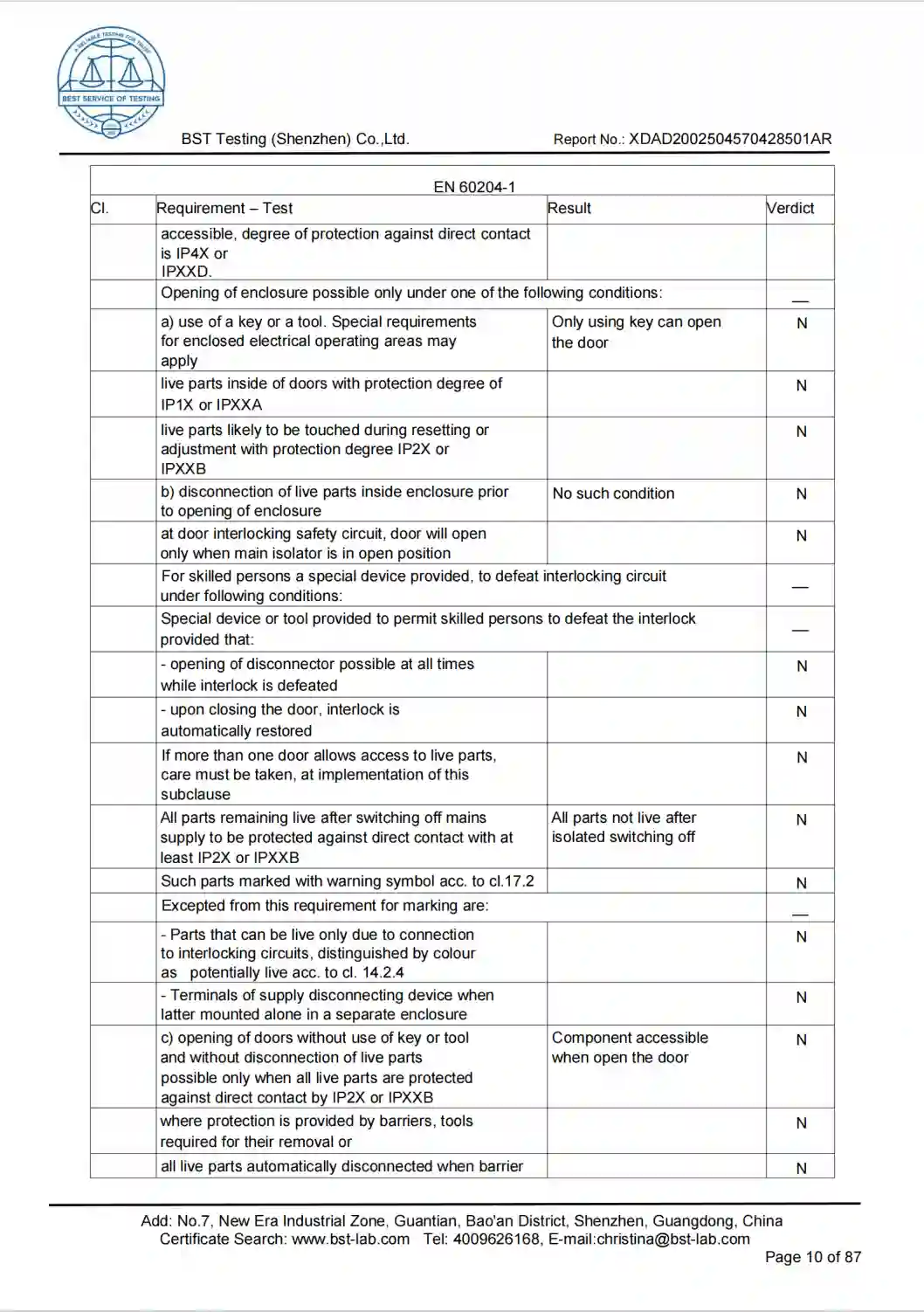
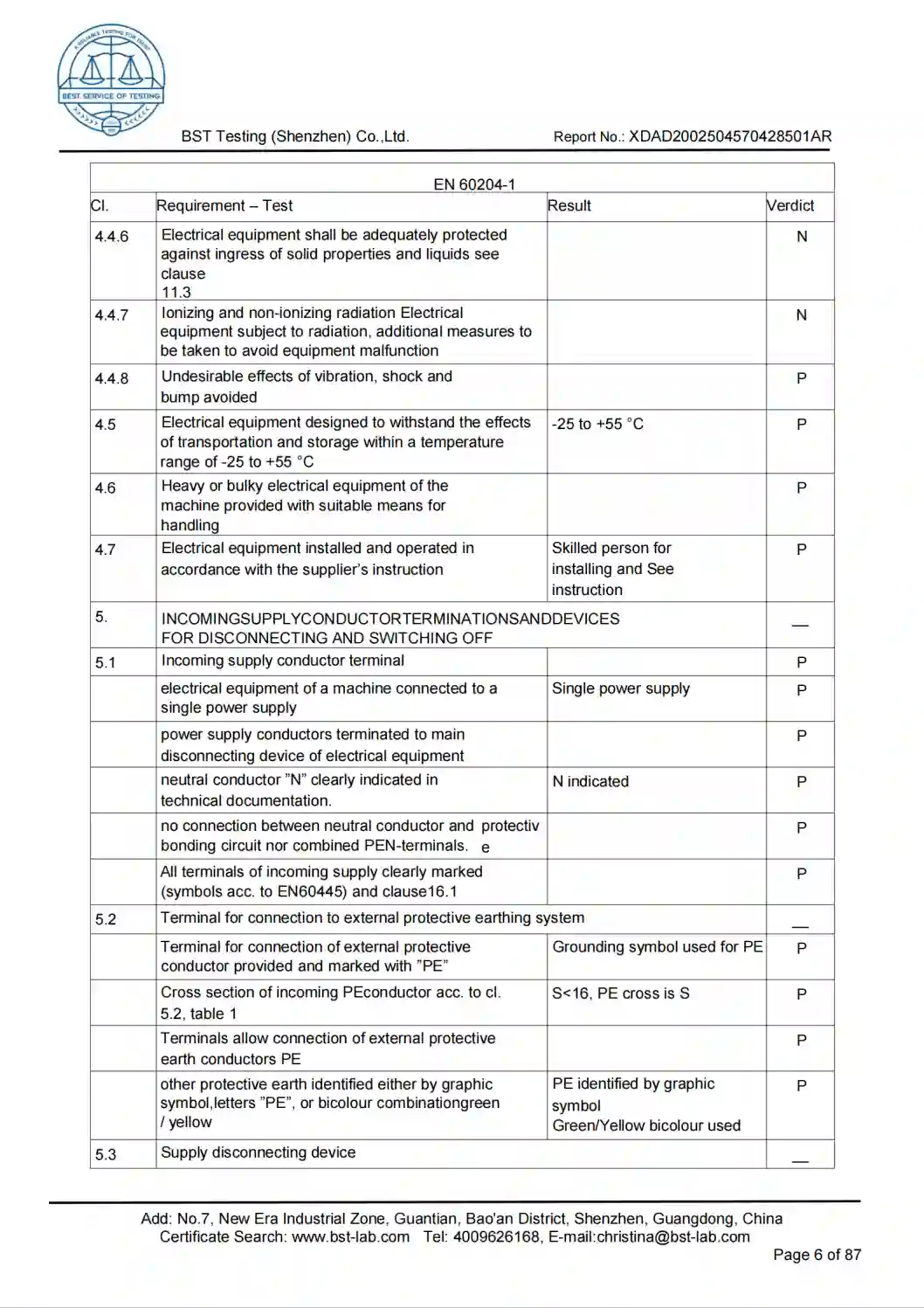
Quality Documentation
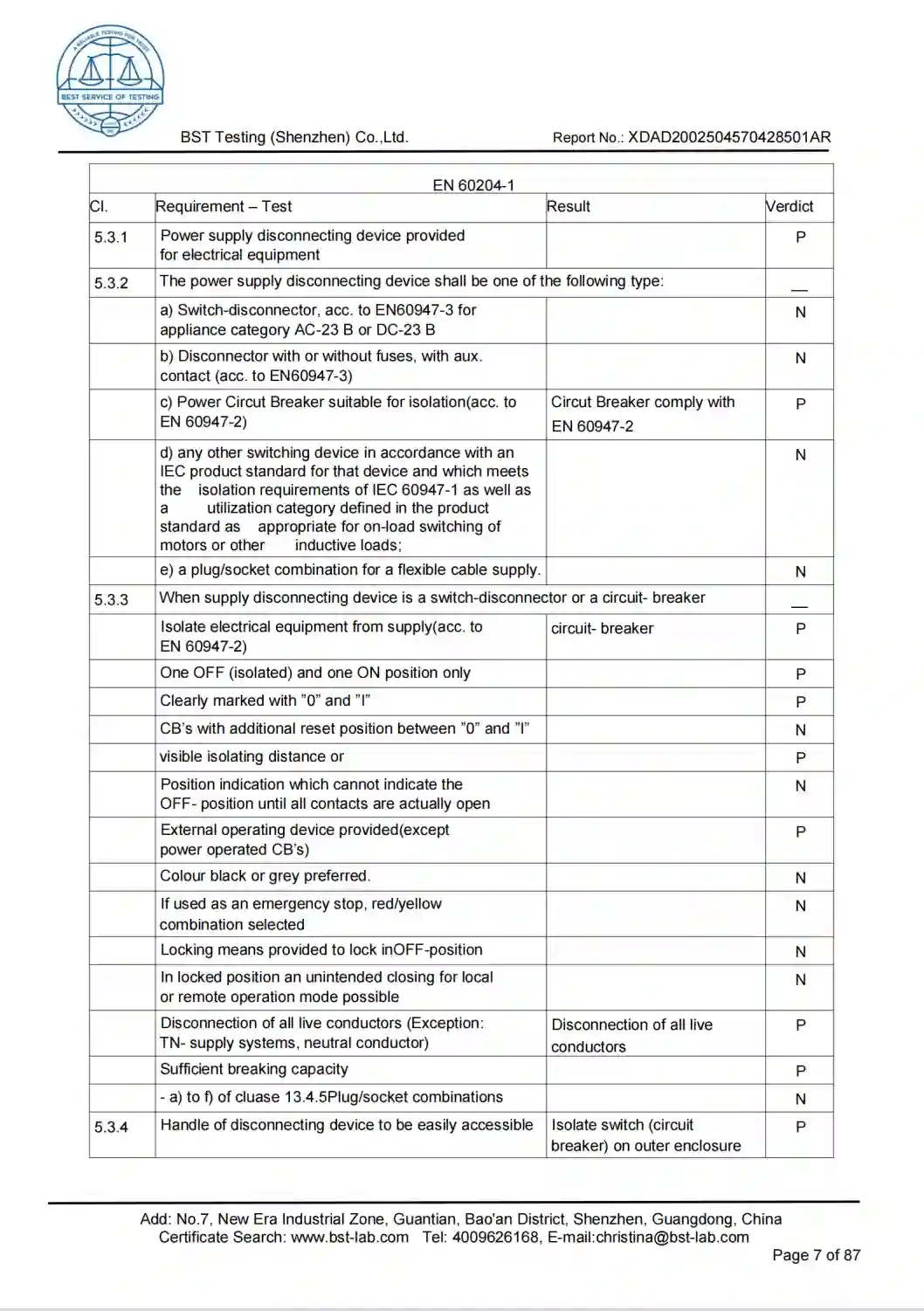
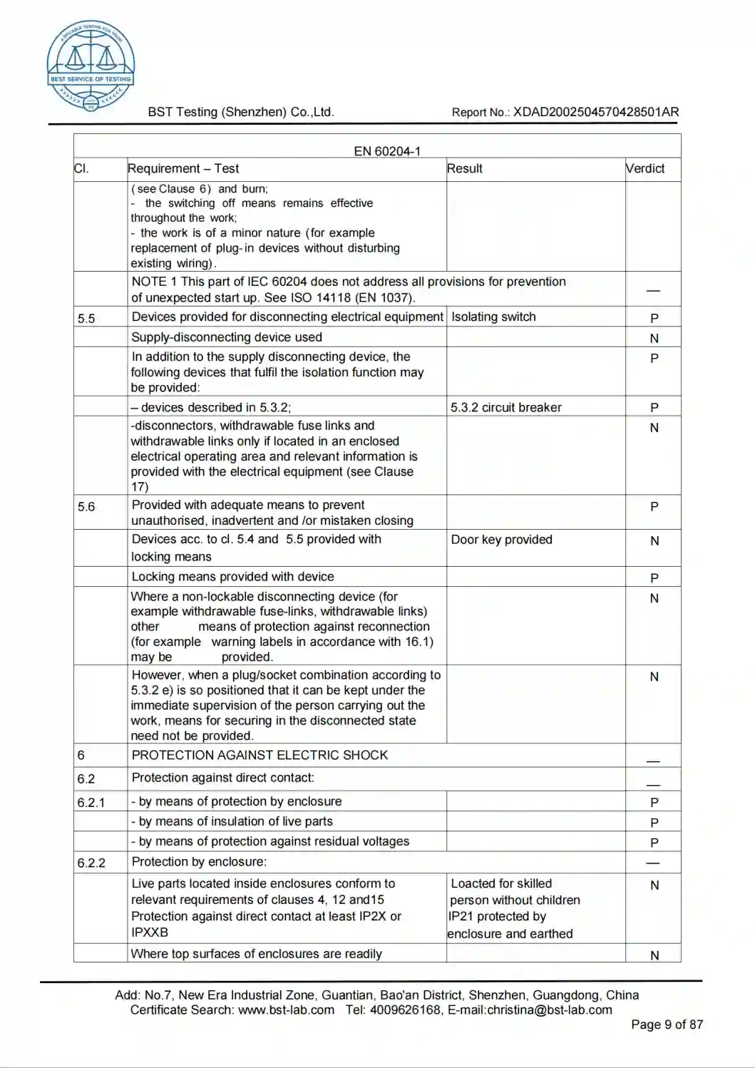
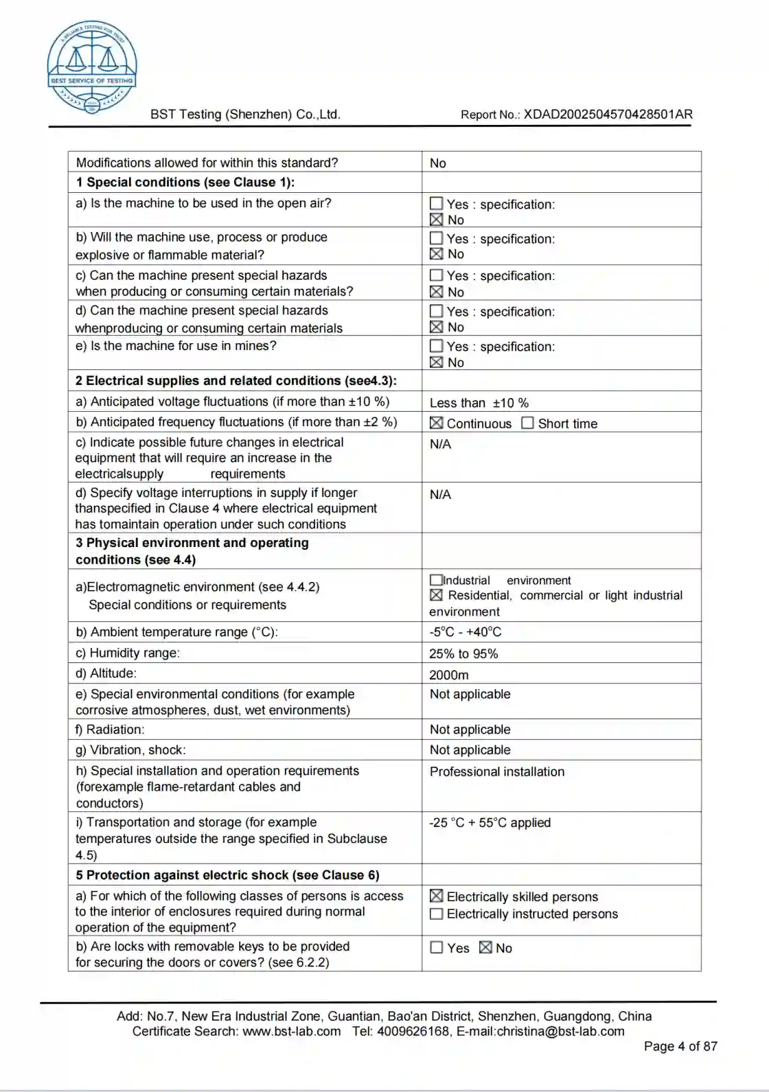
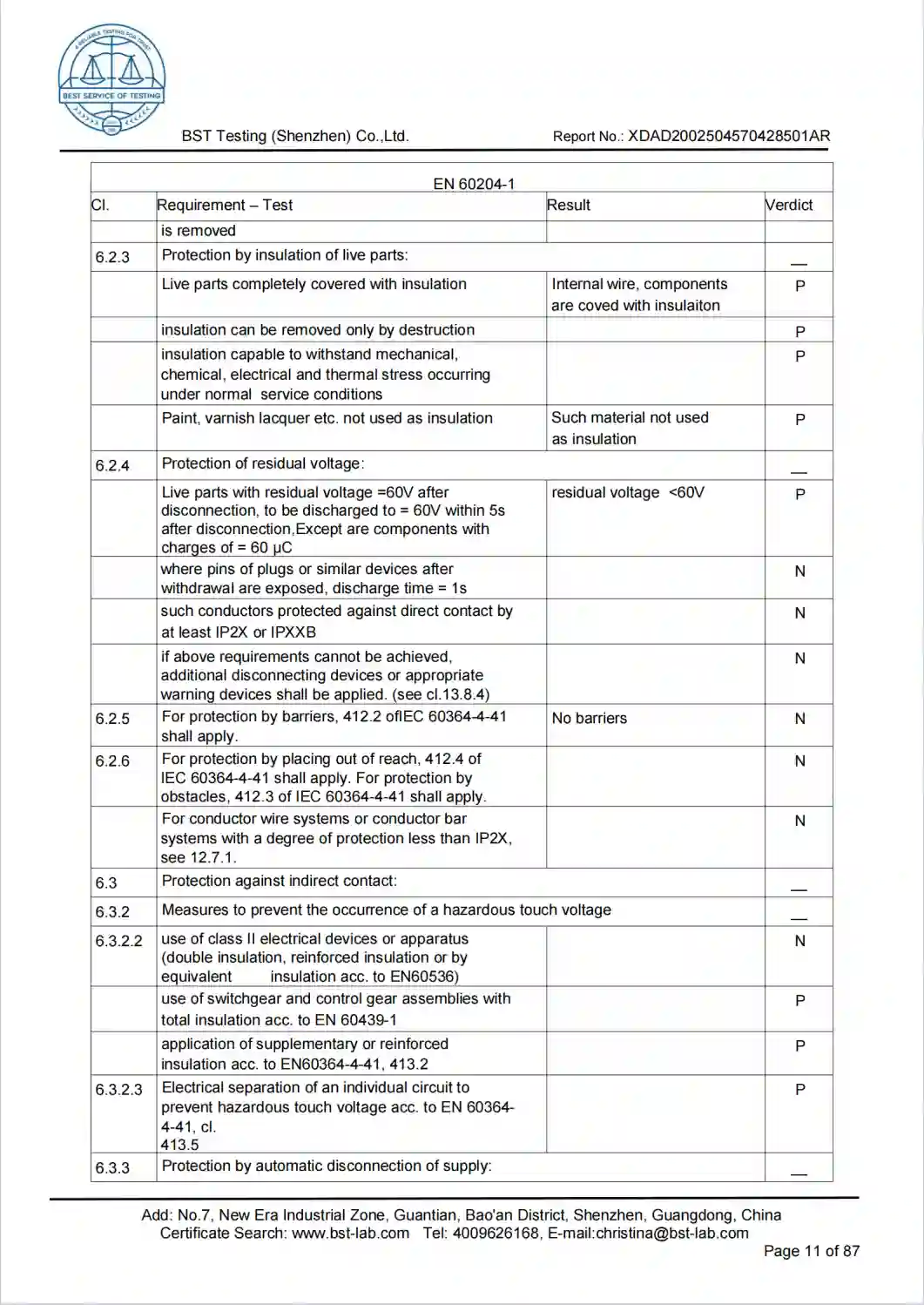
Company Certificates
Production View
Factory Inventory and Production Line
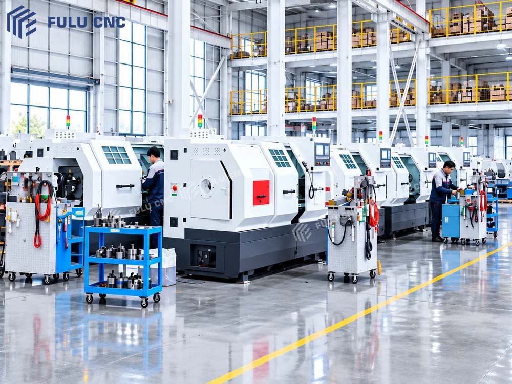 Add factory image URL
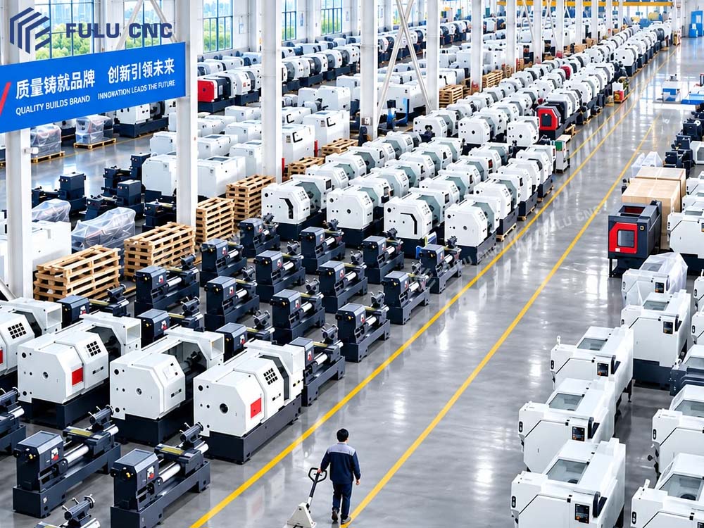 Add production image URL
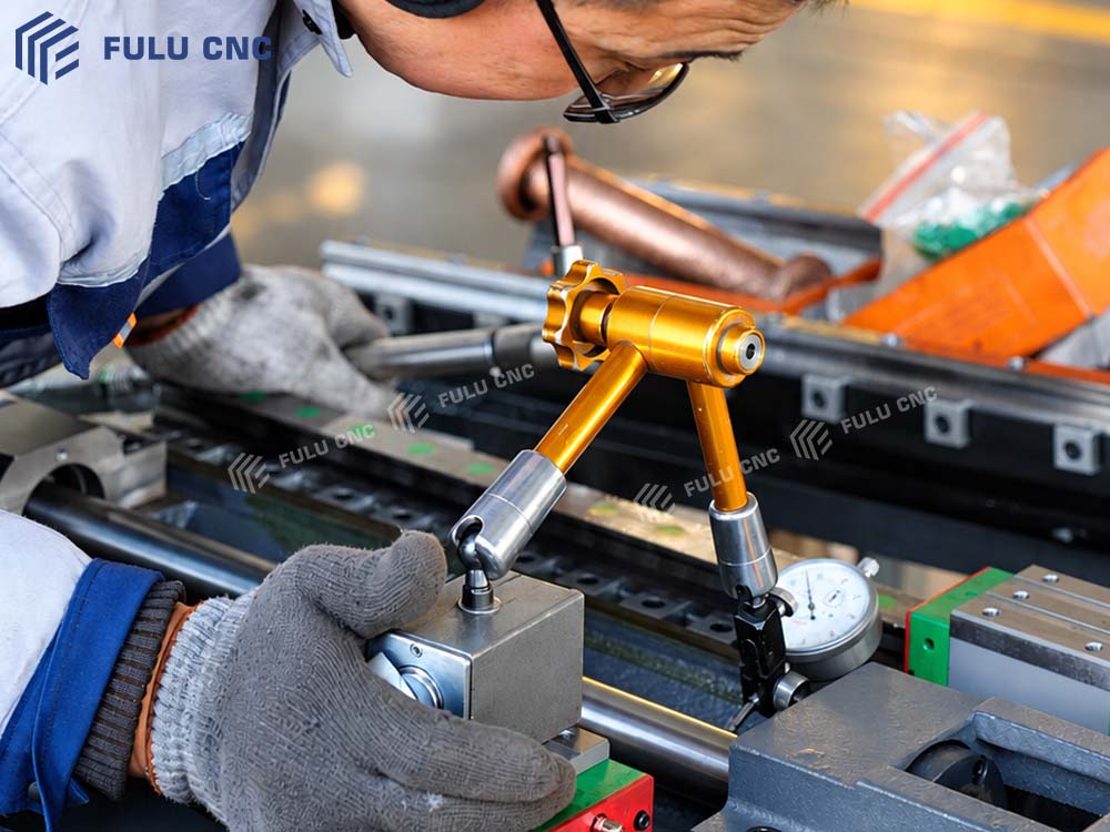 Add inspection image URL
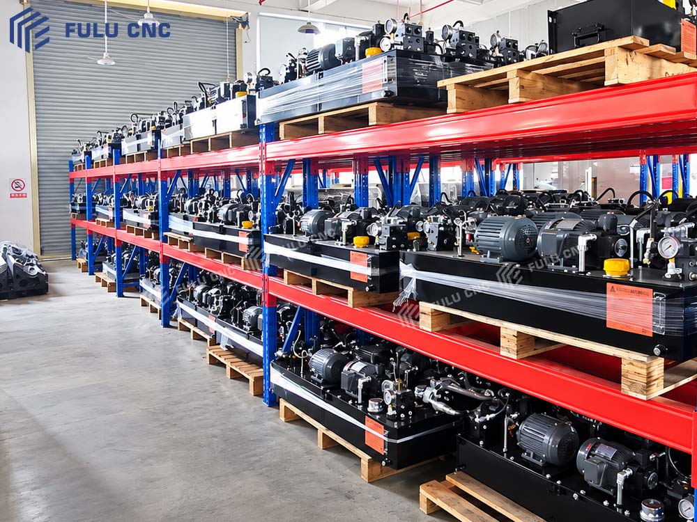 Add component image URL
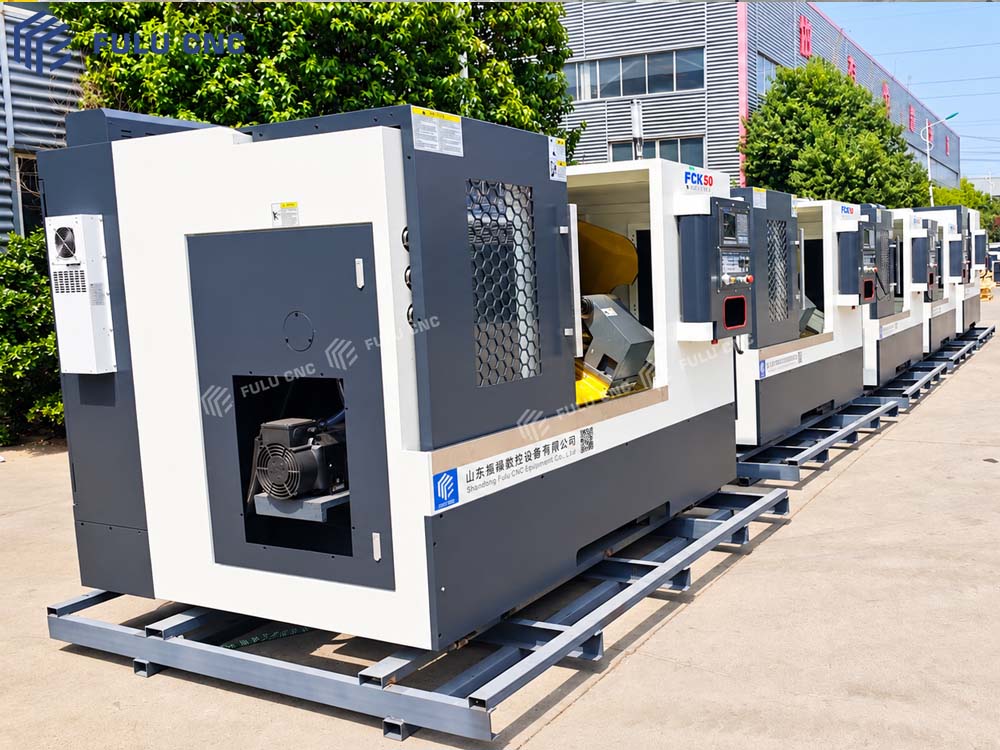 Add completed-machine image URL
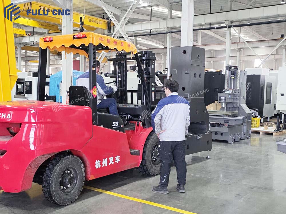 Add production-line image URL
Production Evidence
Inspection, Assembly, and Part Examples
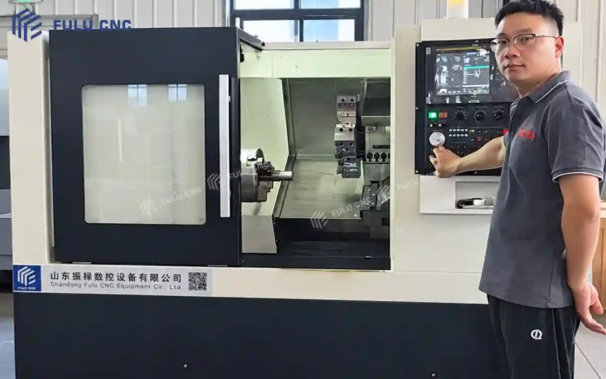
FCK50 inspection record
Positioning and repeatability are guaranteed to the values in the specification table.
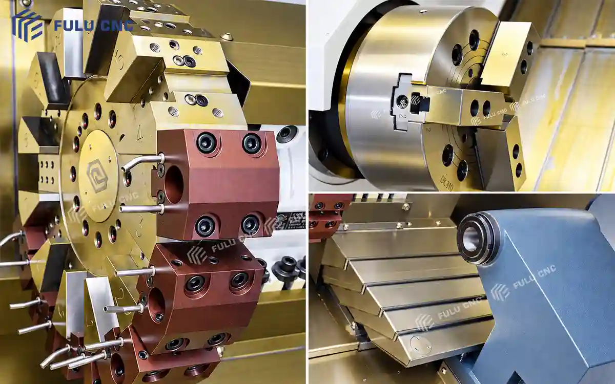
Machine assembly
Review the selected spindle, chuck, turret, and tailstock configuration.
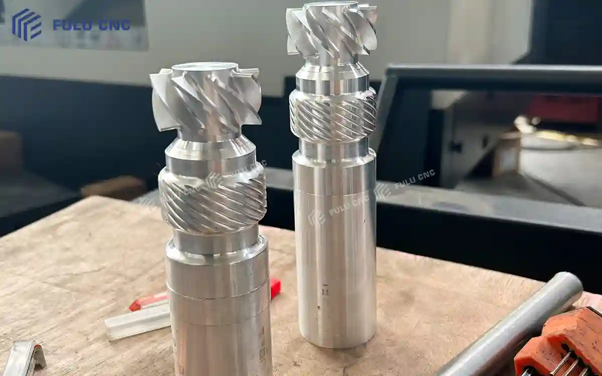
Machined part example
Check part material, workholding, tooling, and acceptance criteria against the drawing.