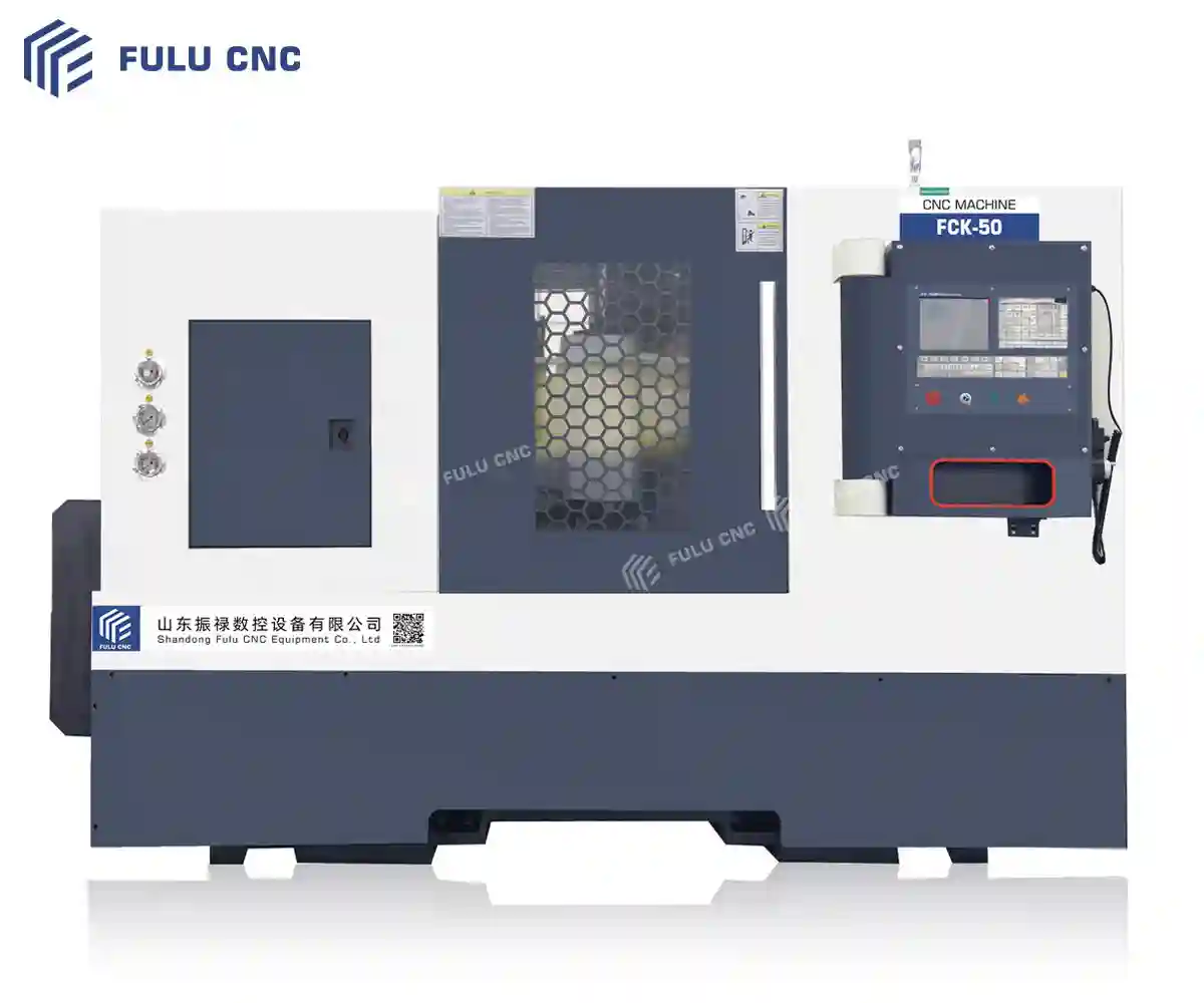
CNC Lathes
For rotational parts requiring CNC turning, boring, facing, or threading. Compare bed structure, turning capacity, tooling, and production requirements.
- CK seriesFlat-bed CNC lathes
- TCK / FCK seriesSlant-bed CNC lathes


FULU CNC Product Selection
Explore CNC lathes, machining centers, conventional machine tools, and wire-cut EDM. Compare each family by workpiece, process, working range, and production requirements before confirming a model configuration.
Machine Families
Four product families cover CNC turning, machining centers, conventional turning and milling, and wire-cut EDM. Start with the process and part geometry, then confirm the exact model and configuration with our team.
For rotational parts requiring CNC turning, boring, facing, or threading. Compare bed structure, turning capacity, tooling, and production requirements.
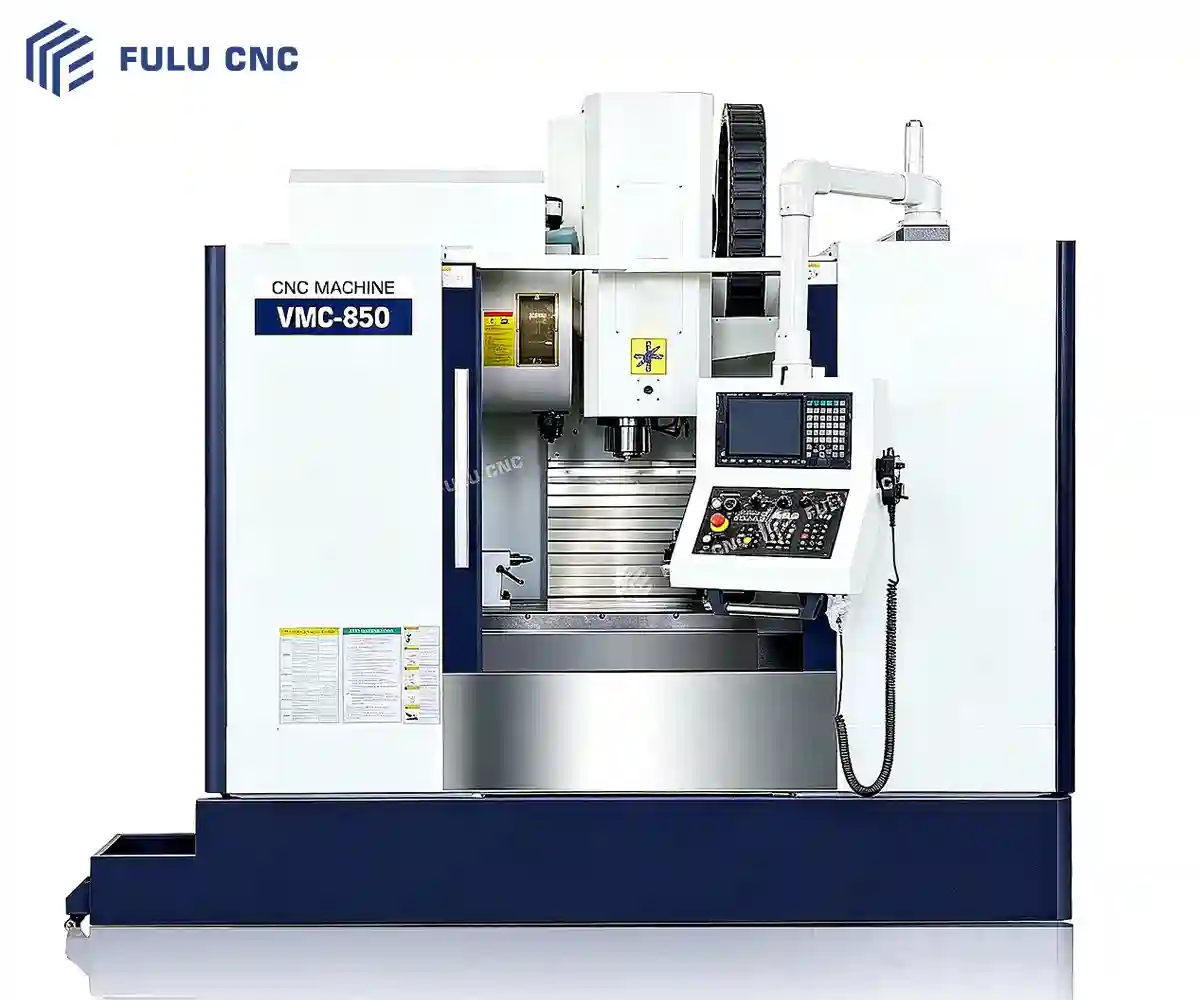
For prismatic and large-format parts needing CNC milling, drilling, tapping, and contouring. Choose by access, work envelope, table load, and setup.
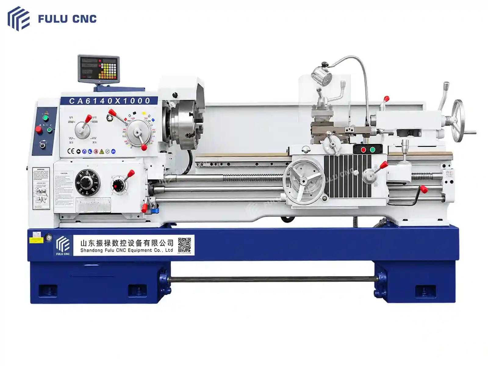
Manual and conventional machines for turning, milling, and drilling work where CNC automation is not required.
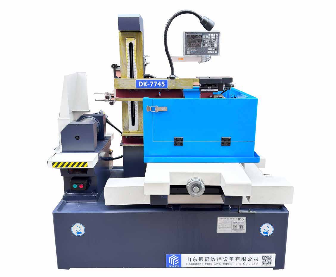
For precision profiles and internal or external contours in electrically conductive materials. Confirm workpiece size, cut requirements, wire system, and finish.
Model availability, controller, tooling, automation, and standard-versus-optional equipment must be confirmed for the selected configuration.
Product Selection Path
A machine name alone does not establish fit. Begin with the part and machining sequence, then confirm the working envelope, production context, and acceptance requirements.
Share the drawing, material, maximum dimensions, weight, tolerance, and required surface finish.
Identify turning, threading, milling, drilling, tapping, contouring, and the intended process sequence.
Confirm turning diameter and length, or travel, table size, load, clearance, and workholding space.
State batch size, setup frequency, cycle target, tooling, automation, controller, and acceptance needs.
| Starting Part / Process | Initial Machine Route | Confirm Before Selection |
|---|---|---|
| Rotational partsTurning, facing, boring, or threading | CNC Lathes | Diameter, length, bore, chuck or workholding, tooling, volume, and process sequence |
| Pipe and thread workPipe-related turning and thread requirements | CNC Lathes (CK / TCK / FCK) | Pipe diameter, length, bore, thread standard, pitch range, workholding, and inspection method |
| Prismatic partsMilling, drilling, tapping, or contouring | Machining Centers (VMC / HMC) | X/Y/Z envelope, table and load, spindle and tool requirements, fixtures, and optional-axis needs |
| Large workpiecesBroad surfaces or larger access requirements | Gantry Machining Centers (GMB) | Part size and weight, travel, table, head access, setup plan, lifting, and foundation requirements |
| Manual turning, milling, or drillingConventional production, repair, or one-off work | Conventional Machine Tools (CA / CW / X / ZX) | Workpiece dimensions, operations, spindle range, table or swing, workholding, and required accuracy |
| Conductive profilesWire-cut contours, slots, or internal profiles | Wire-Cut EDM (DK77) | Material conductivity, workpiece size and thickness, cut geometry, wire system, finish, and accuracy |
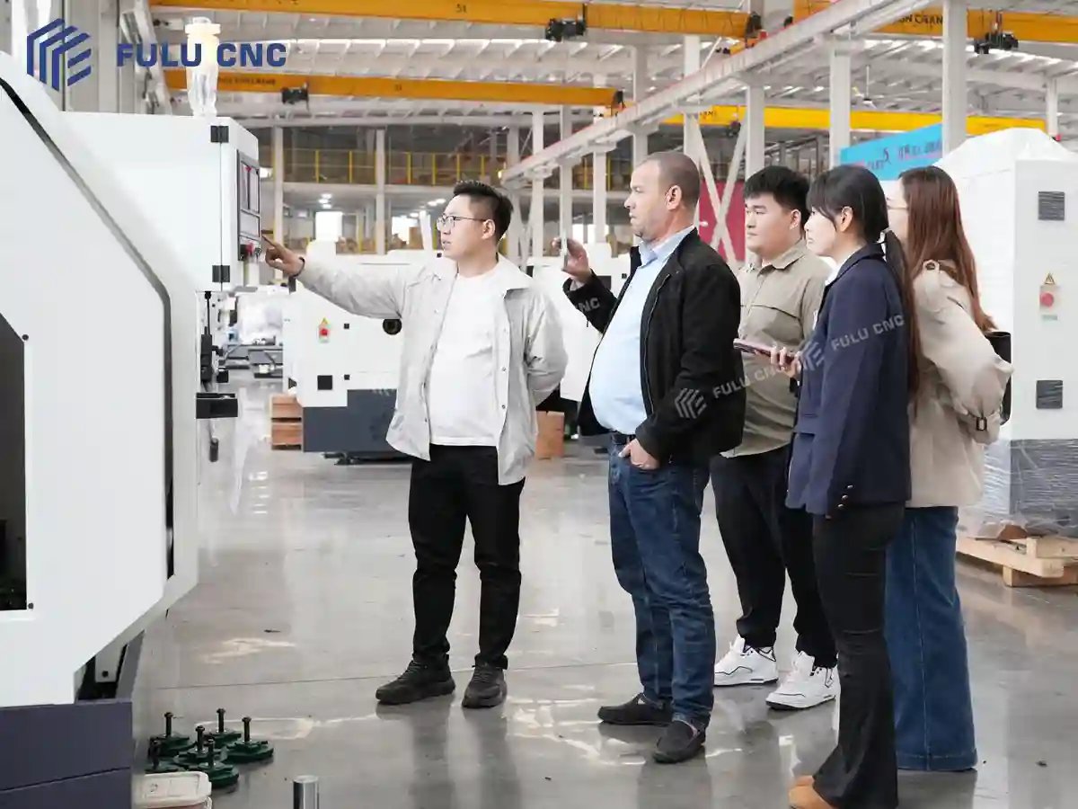
This table identifies a starting family, not a final model. Exact fit must be checked against verified machine data, tooling, workholding, options, and acceptance conditions.
Factory & Quality Evidence
Product selection should be supported by factory evidence and a clear inspection path. Review how machines are assembled, checked, documented, and prepared for the agreed acceptance scope.
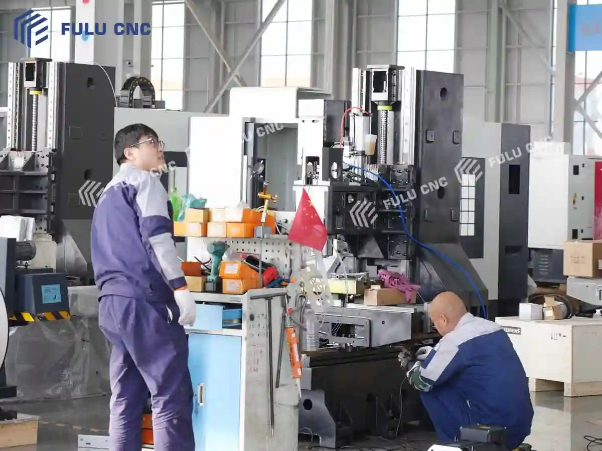
Use original workshop and process evidence to understand where assembly, alignment, calibration, testing, and final preparation take place.
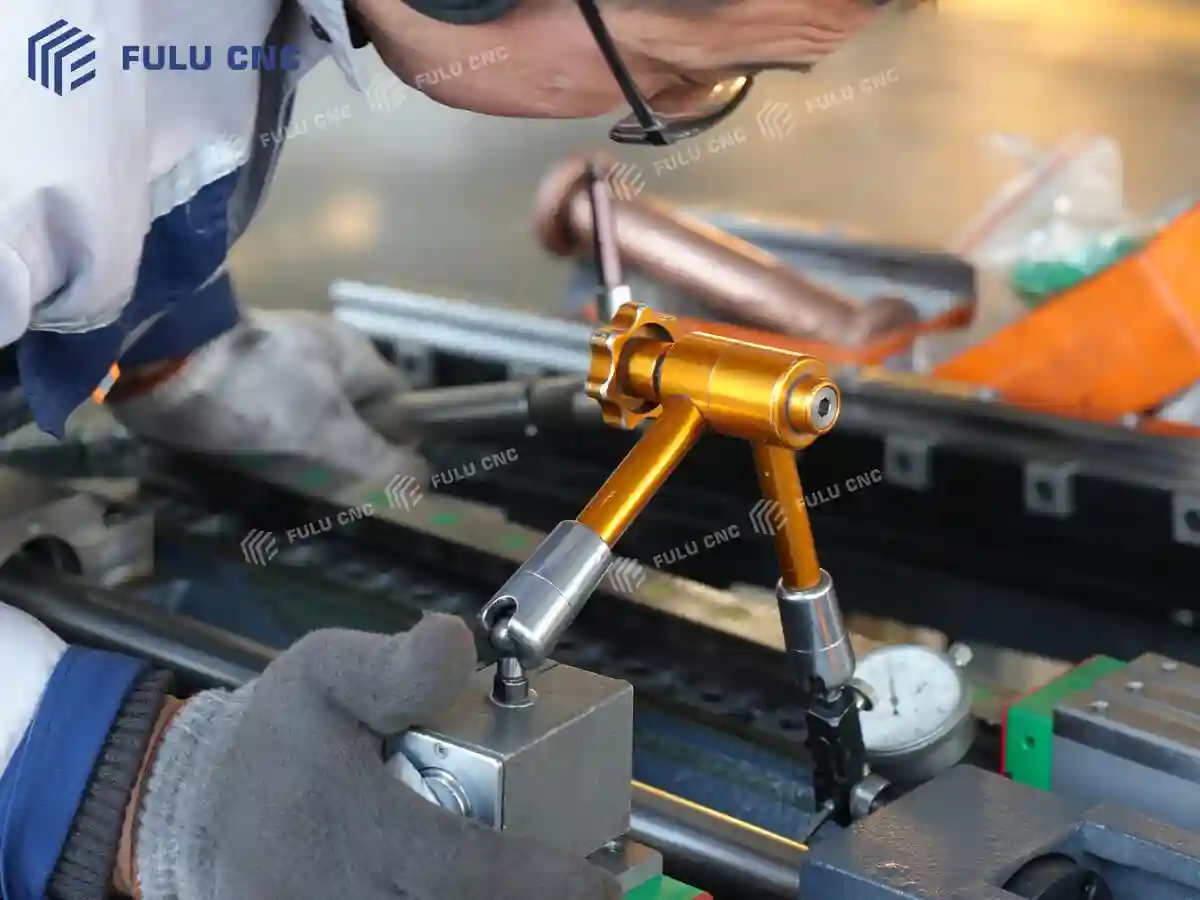
Confirm which checks apply to the selected machine, which instruments and conditions are used, and which records form part of the agreed acceptance package.
Engineering & Customization
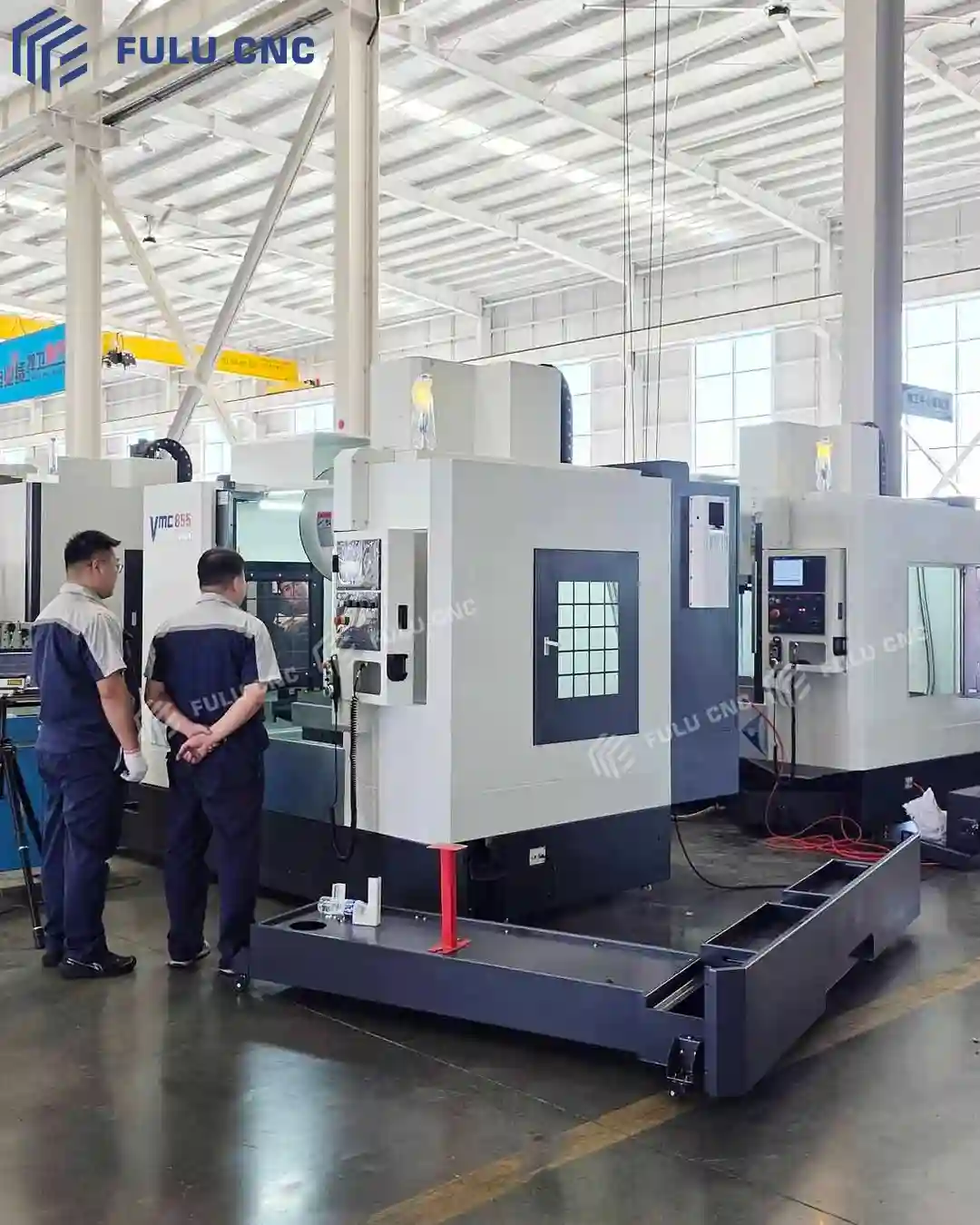
Configuration review starts with the part and production requirements. The review should separate standard equipment, selectable options, third-party items, custom-engineering work, and details still requiring confirmation.