Vertical Machining Center

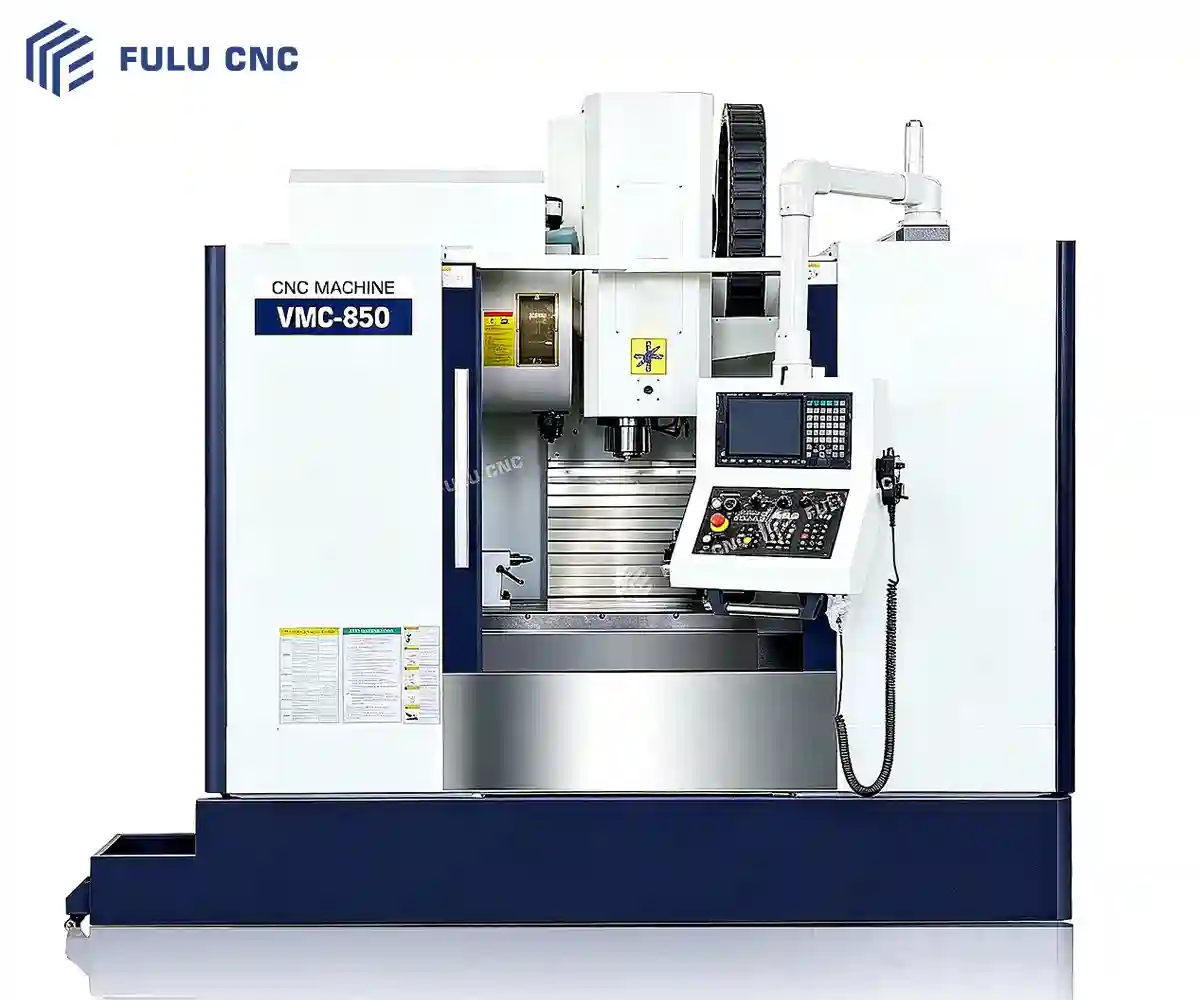
VMC850 Vertical Machining Center

Machine prismatic components on a 1,000 × 500 mm table with 800 × 500 × 500 mm X/Y/Z travel. The VMC850 combines a BT40 spindle, an 8,000 r/min maximum spindle speed, and a 500 kg maximum table load for milling and drilling work within its verified envelope.

800 × 500 × 500 mmX/Y/Z travel
1,000 × 500 mmTable size
500 kgMaximum table load
BT40 / 8,000 r/minSpindle taper / maximum speed

Check fixture height, tool reach, workpiece mass, and the selected spindle motor before final machine selection.

Part and Process Fit

Suitable Workpieces and Applications

Start with the complete workpiece and fixture envelope, then match the operations to spindle, tool, and access requirements.

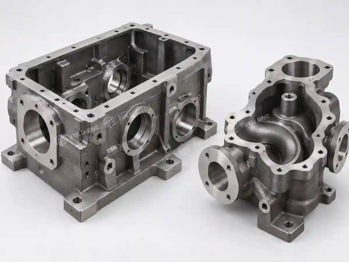
Box-Type Parts

Gearbox housings with multiple bores, internal cavities, and mounting faces; pump and valve bodies with irregular cavities, flow passages, and flange faces.
Plates, Discs, and Flanges

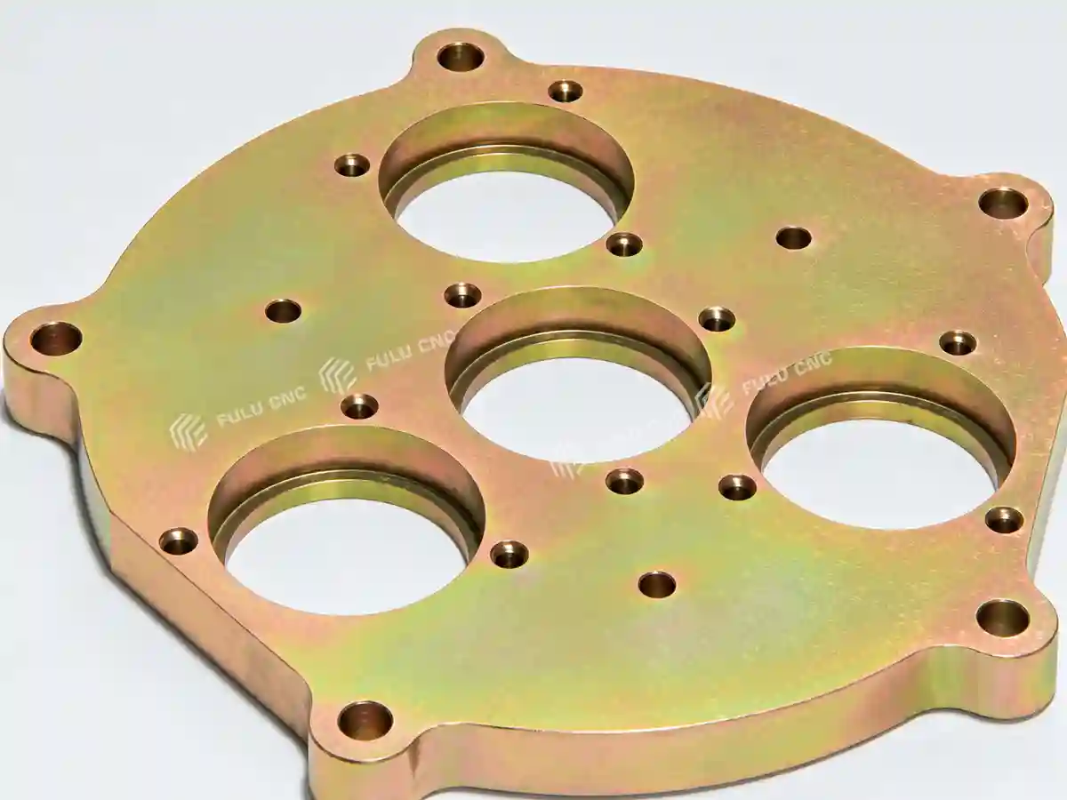
Mounting plates and panels with hole patterns, counterbores, and flat slots; flange plates and end covers with circular profiles, bolt circles, and locating features.
Irregular Brackets and Supports

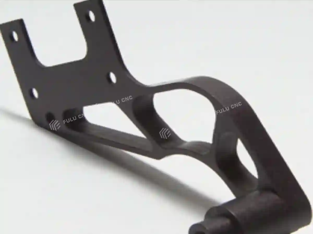
L- and T-shaped brackets, stepped connection seats, side holes, bearing housings, and vertical supports with mounting faces and semi-circular or circular bores.
Mold Components

Plastic mold cavities and cores with deep pockets, ribs, and contoured surfaces; mold bases and ejector plates with guide-pin and ejector-hole patterns.
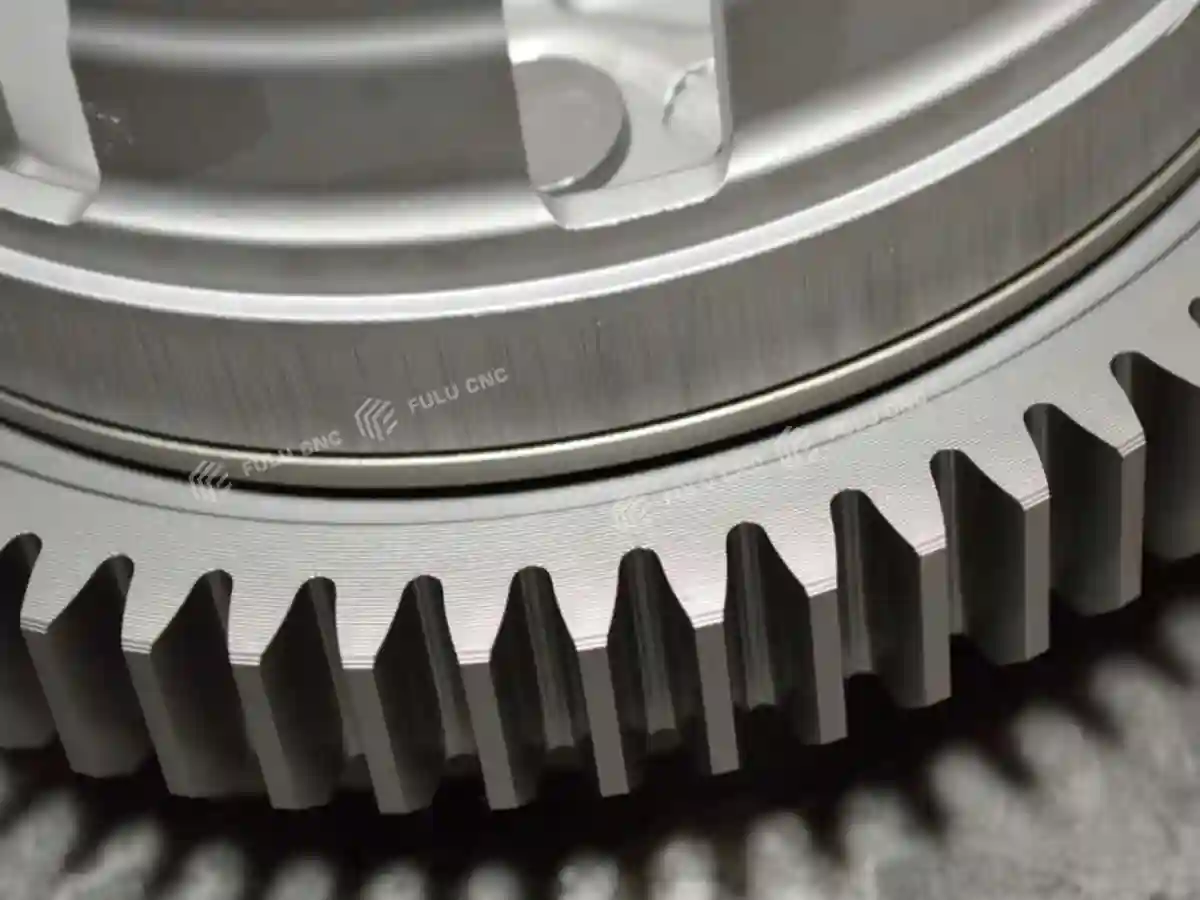
Complex Contoured Parts

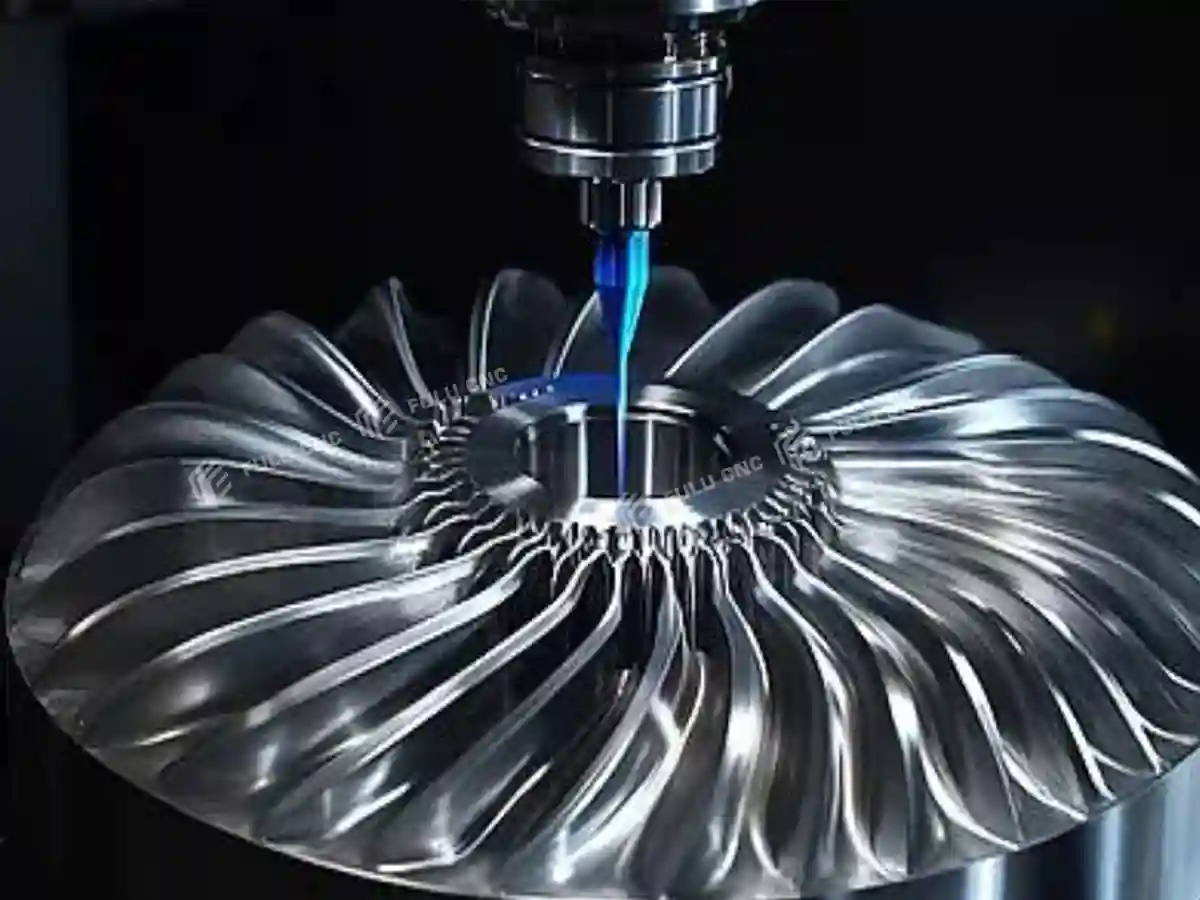
Impellers and blades with twisted surfaces and flow passages; turbine and fan wheels with multiple blades and annular contours.
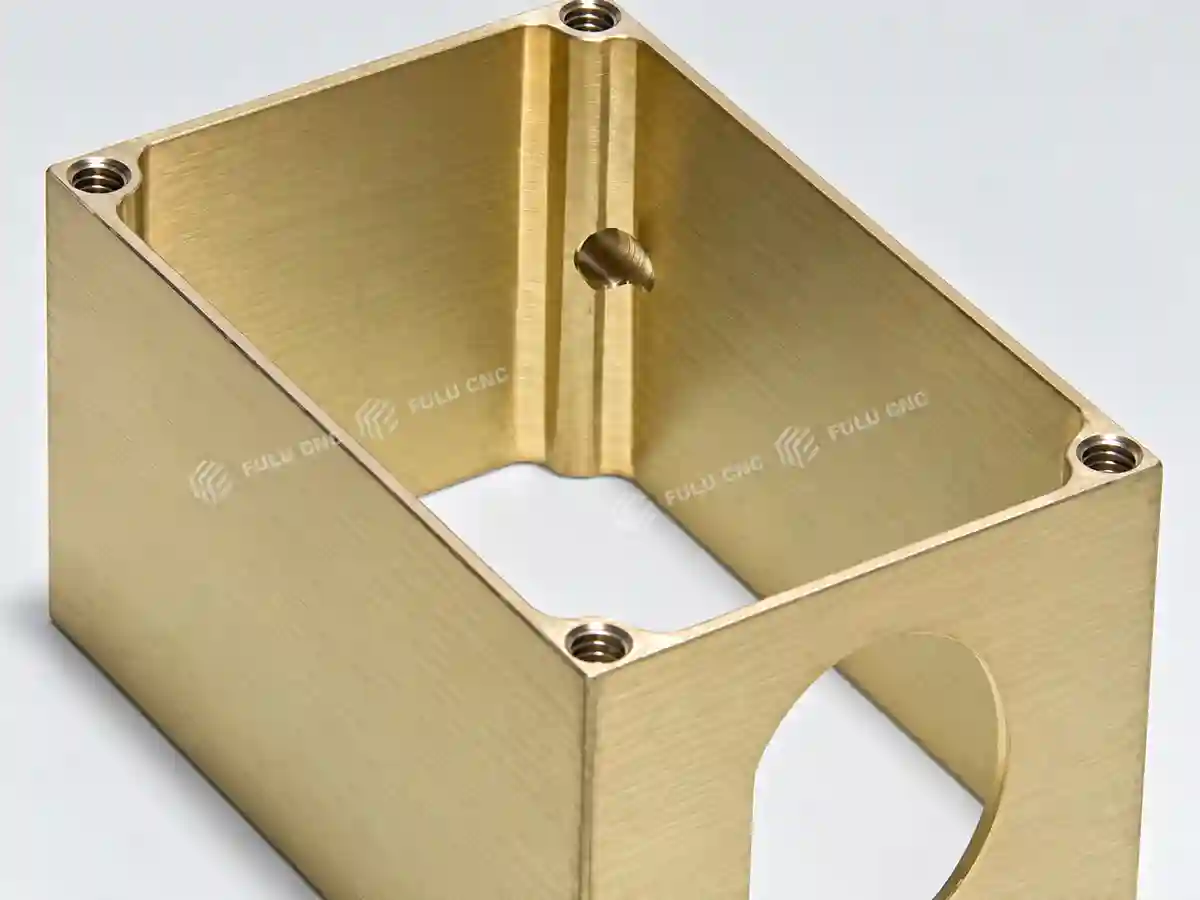
Precision Parts and Aluminum Housings

Thin-wall aluminum enclosures and controller housings with cavities, interface holes, and multi-directional slots; hydraulic manifolds with cross-drilled holes and sealing faces.

Initial fit

Use the 800 × 500 × 500 mm travels and 130–630 mm spindle-nose-to-table distance for an initial layout check.

Engineering review

Deep cavities, tall fixtures, heavy off-center loads, long tools, and side-face operations need a process and interference review.

Model Selection

Choose the Correct VMC Size

These three catalog models differ most clearly in travel, table area, load capacity, and spindle-to-table clearance.

ModelX/Y/Z travelTable and loadSelection direction
VMC850800 / 500 / 500 mm1,000 × 500 mm; 500 kgParts that fit the VMC850 envelope without paying for a larger table.
VMC855800 / 550 or 600 / 550 or 580 mm1,000 × 550 mm; 600 kgMore Y/Z space and table load while retaining 800 mm X travel.
VMC11601,100 / 600 / 600 mm1,200 × 600 mm; 1,000 kgLonger or heavier parts that exceed the smaller machines.

Available VMC855 travel combinations and each model's final motor configuration should be confirmed in the quotation.

Machine Construction

VMC850 Design Advantages

01

BT40 spindle for a defined tooling interface

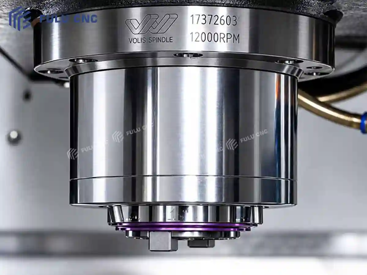
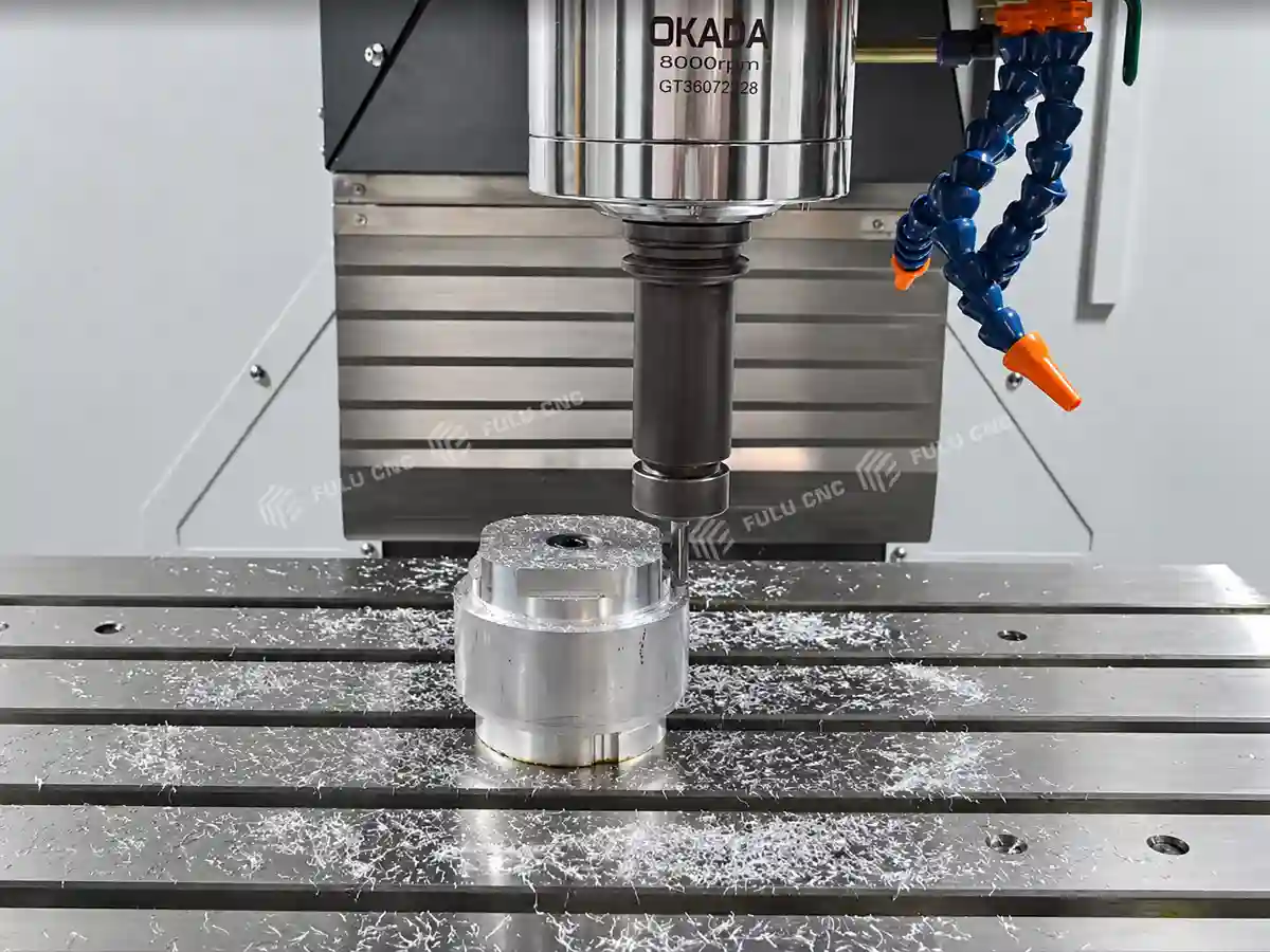
The catalog specifies a BT40 spindle taper and up to 8,000 r/min. A defined taper helps the buyer plan compatible holders and tools for milling, drilling, and boring operations. The appropriate speed, tool reach, and cutting data still depend on material, cutter, holder, and the selected 7.5 or 11 kW spindle-motor configuration.
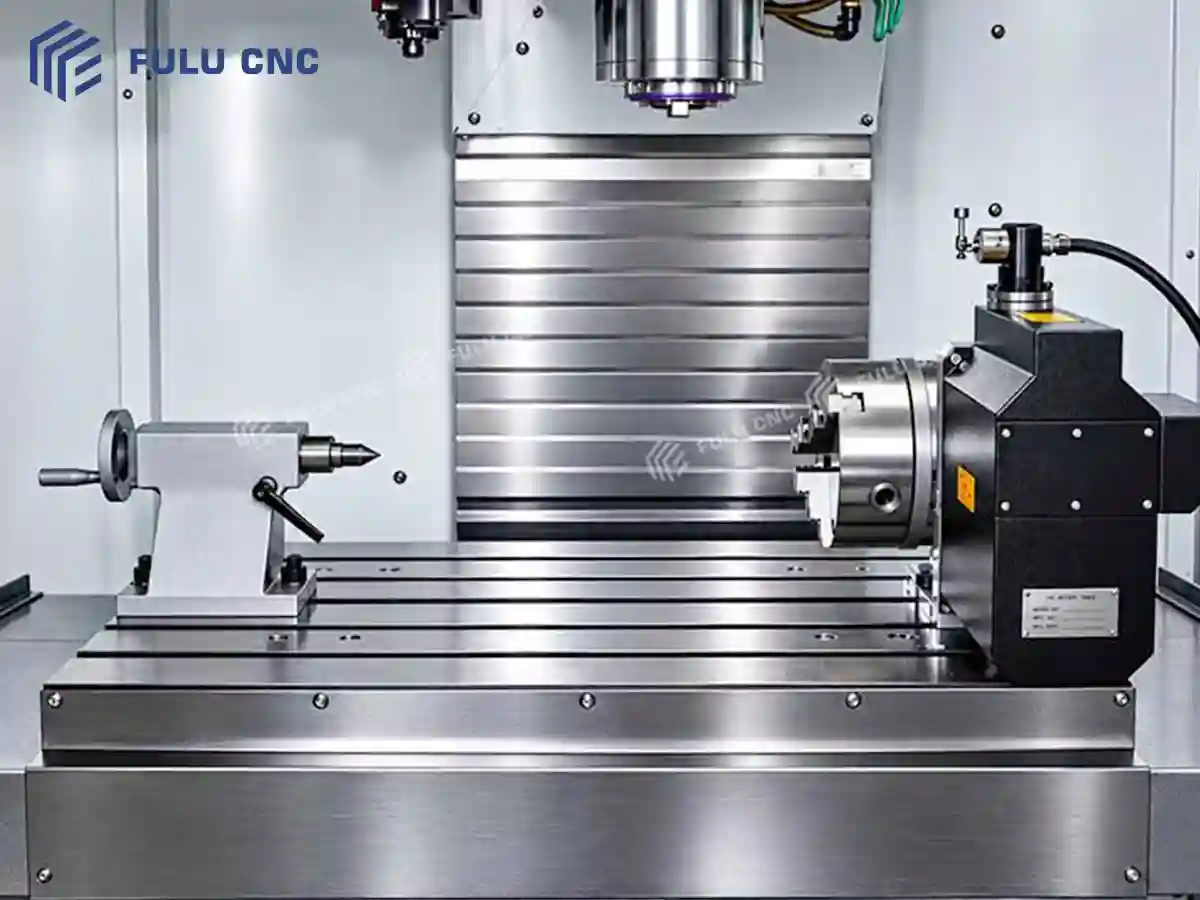
02

Table and travel sized for prismatic parts

The 1,000 × 500 mm table, five 18 mm T-slots at 100 mm pitch, and 800 × 500 × 500 mm travel allow a fixture to be planned around the part and the required cutting path. The 500 kg maximum table load is a selection limit; fixture mass and load distribution count toward it.
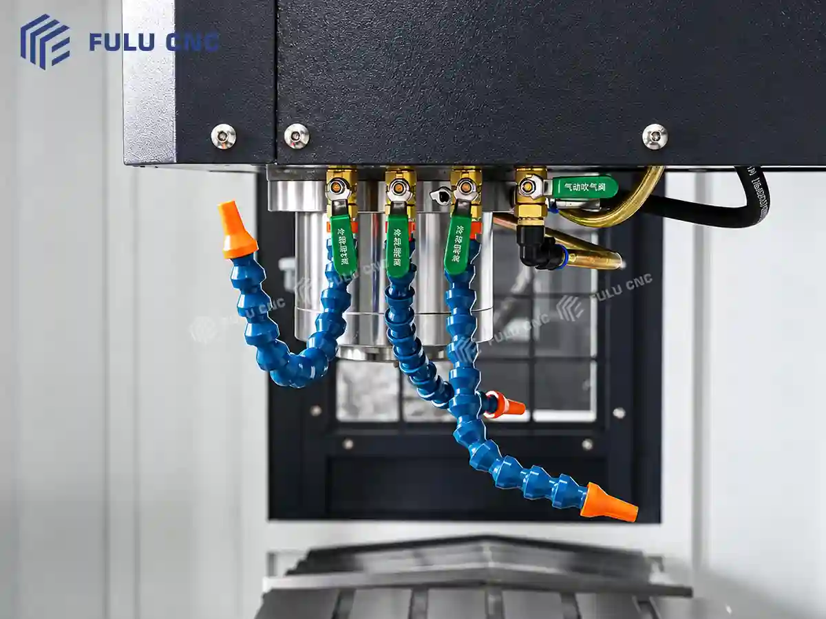
03

Standard coolant and chip clearing support

The standard configuration includes a cutting coolant system, a spindle-mounted coolant ring, and an air-blow device. These provide ways to direct fluid and air into the working area during milling and drilling, supporting chip removal and work visibility. Coolant delivery at the tool tip depends on tool geometry, nozzle setup, and the selected cutting process.

04

Three-axis screw preload and automatic lubrication

Preloaded ball screws on all three axes and automatic lubrication are listed as standard. Screw preload helps control axial play in the feed system, while automatic lubrication supplies the machine's lubrication points during operation. Actual positioning results depend on installation, temperature, maintenance, and the agreed inspection method.
05

Protection and preparation for planned upgrades

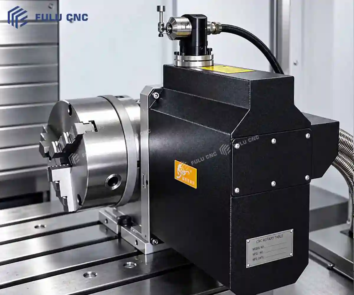
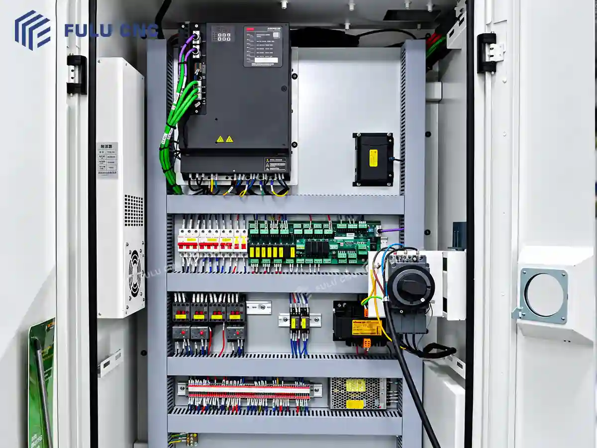
Standard equipment includes spindle and servo overload protection, an electrical-cabinet heat exchanger, and a pre-wired fourth-axis interface. These features support machine operation and simplify planning for a future rotary-axis project. A usable fourth axis is not included by the interface alone; table, drive, controller functions, and installation require separate confirmation.

Machine Data

VMC850 Technical Specifications

Work Envelope and Table

ParameterUnitVMC850
X / Y / Z travelmm800 / 500 / 500
Table sizemm1,000 × 500
Maximum table loadkg500
T-slots: number × width × pitchmm5 × 18 × 100
Spindle nose to tablemm130–630
Spindle center to column guideway surfacemm525

Spindle, Feed, and Tool Limits

ParameterUnitVMC850
Spindle taper—BT40
Spindle motor configurations listedkW7.5 / 11; selected rating to be specified in quotation
Maximum spindle speedr/min8,000
Cutting feed rangemm/min1–8,000
Maximum tool diameter, adjacent / empty pocketsmm78 / 120
Maximum tool lengthmm300
Maximum tool weightkg8

Machine and Installation

ParameterUnitVMC850
Approximate machine weightkg5,600
Overall dimensions, L × W × Hmm2,600 × 2,300 × 2,800
Positioning and repeatability—Inspection method and acceptance values to be agreed for the ordered machine

Standard Equipment

SystemStatus
Cutting coolant system; spindle-mounted coolant ring; air-blow deviceStandard
Automatic lubrication; preloaded ball screws on three axesStandard
Spindle and servo overload protection; three-color tower lightStandard
Electrical-cabinet heat exchanger; internal work lightStandard
Leveling bolts and pads; program storageStandard
Pre-wired interface for a fourth axisStandard interface only

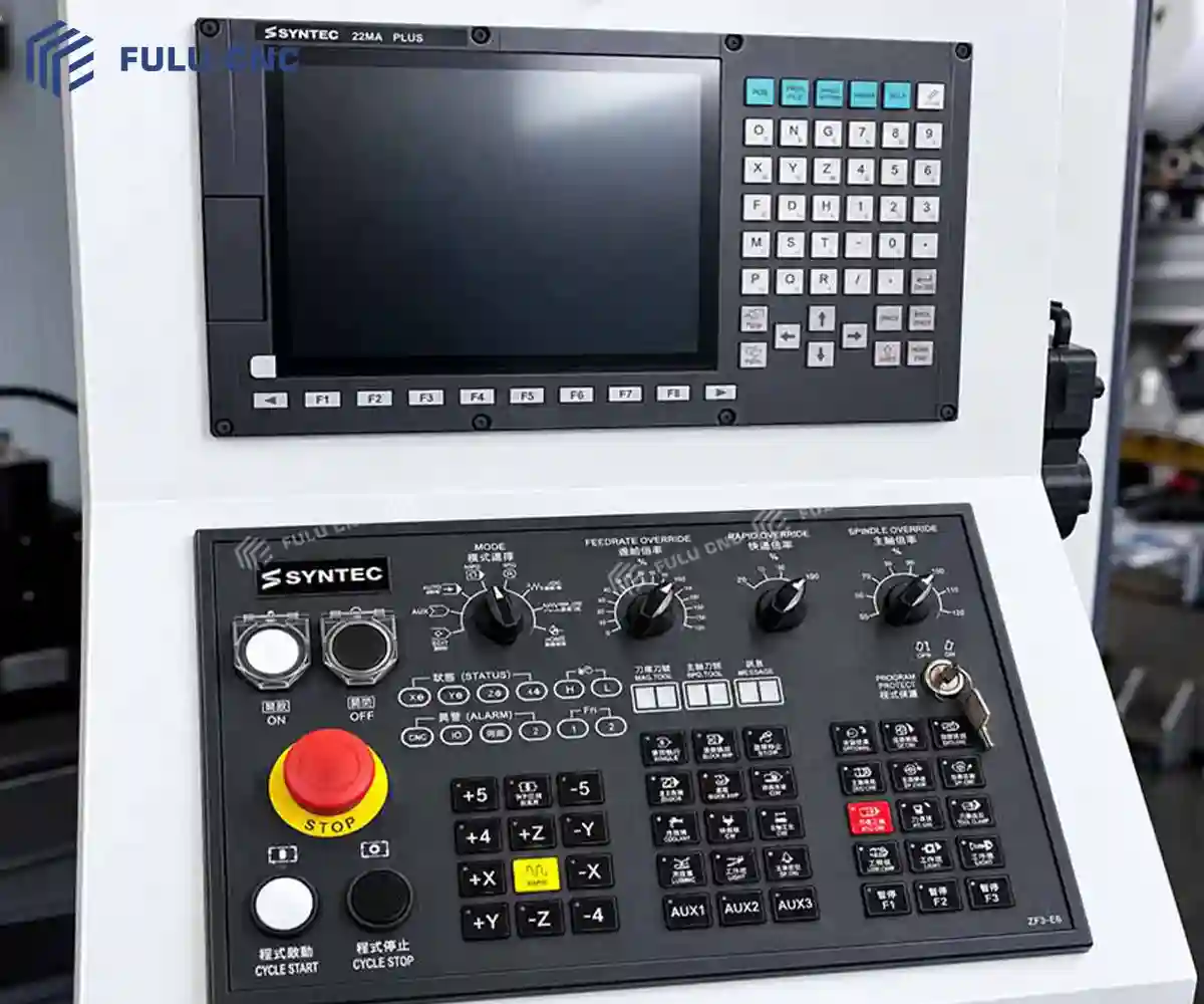
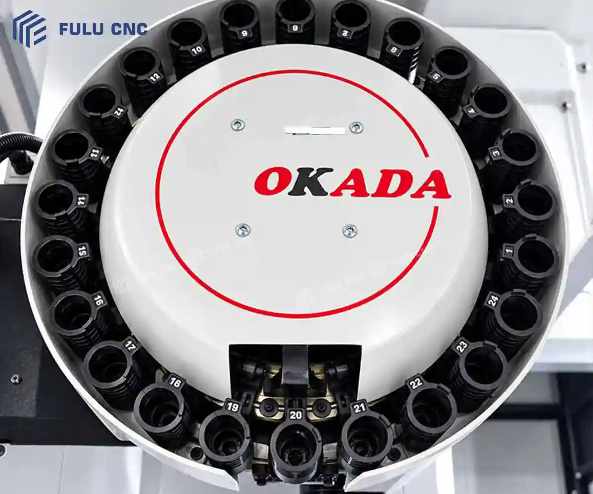
Tool magazine capacity, CNC control model, through-spindle coolant, rotary table, probing, and chip conveyor are not specified for this VMC850 catalog configuration. Include required items in the technical inquiry.

Application Review

Quick Selection Guide

Buyer questionVMC850 checkWhat to send for review
Will the part and fixture fit?Compare their assembled envelope with X/Y/Z travel and 130–630 mm spindle-to-table distance.Part drawing, fixture sketch, stock size, tool reach.
Will the table carry the setup?Part and fixture together must remain within the 500 kg table-load limit.Combined mass and center-of-gravity position.
Is the spindle suitable?BT40, 8,000 r/min maximum; motor rating depends on the selected configuration.Material, cutter diameter, target cut, and cycle requirement.
Are additional axes needed?A fourth-axis interface is standard, but the rotary table and operating configuration require separate specification.Faces to machine, indexing or simultaneous-motion need, part envelope.
Do tolerances need proof?Agree on inspection method and acceptance criteria for the ordered machine.Critical dimensions, tolerances, surface finish, and inspection standard.

Adjacent Models

VMC850, VMC855, or VMC1160?

Decision pointVMC850VMC855VMC1160
X / Y / Z travel, mm800 / 500 / 500800 / 550 or 600 / 550 or 5801,100 / 600 / 600
Table, mm1,000 × 5001,000 × 5501,200 × 600
Maximum table load, kg5006001,000
Spindle nose to table, mm130–630130–660140–740
When to move upStart here when the complete setup fits.Choose more Y/Z space or 600 kg load with 800 mm X travel.Choose longer X travel, a larger table, or a heavier load.

Confirm the exact VMC855 travel combination and every machine's selected equipment before ordering.

Quality Documentation

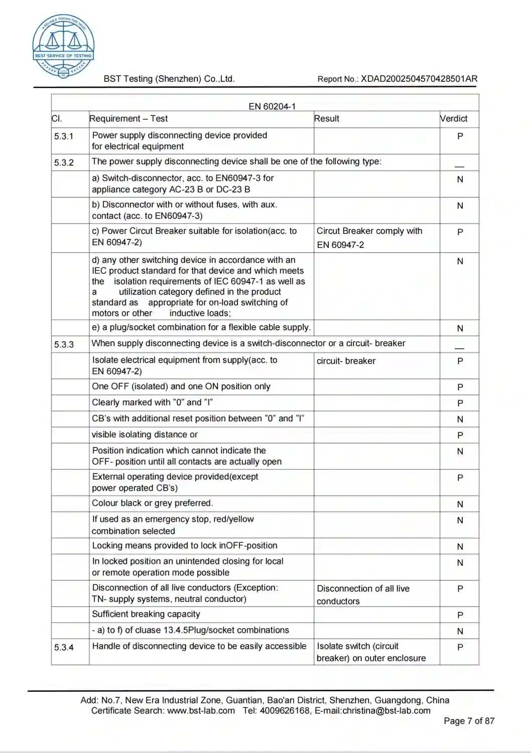
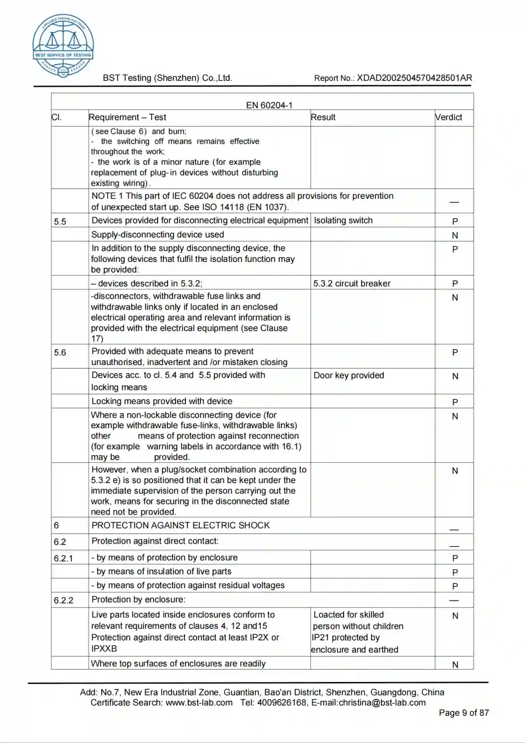
Company Certificates

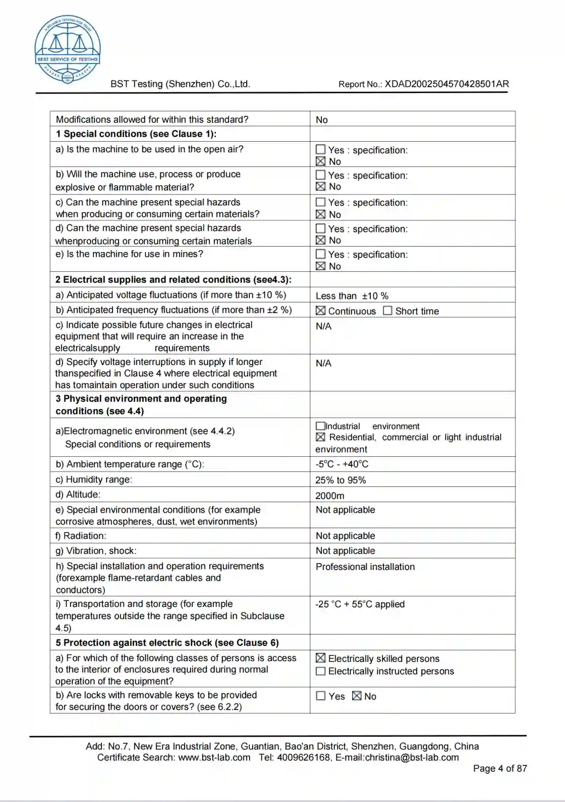
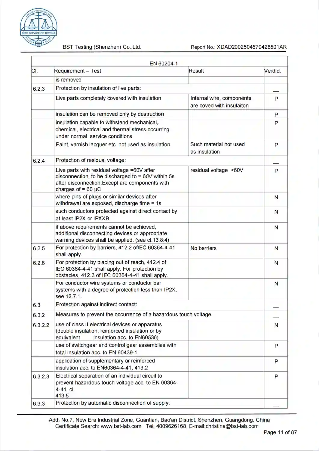
Configuration Evidence

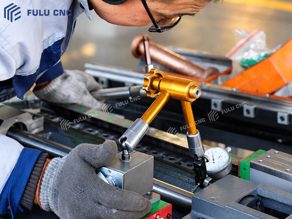
Inspection, Assembly, and Part Examples

Part and fixture layout

Check travel, table area, T-slot pitch, spindle-to-table distance, and tool clearance on a single setup drawing.

Selected equipment list

Confirm the motor rating, CNC control, tool magazine, coolant arrangement, and any rotary-axis equipment in the quotation.
Acceptance plan

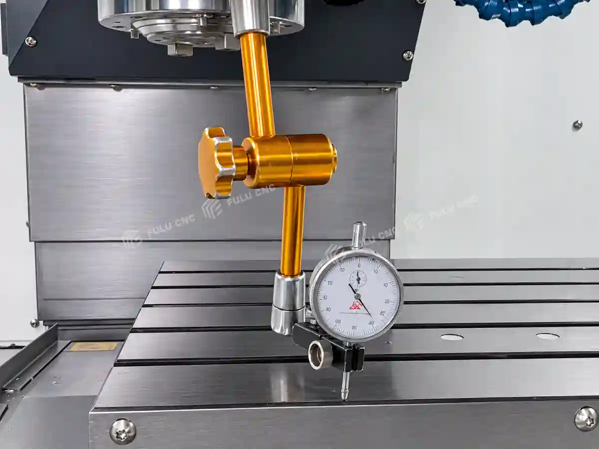
Agree on positioning checks and, when needed, a sample-part inspection plan before production acceptance.
Common Questions

VMC850 FAQ

What are the VMC850 axis travels?

X, Y, and Z travels are 800, 500, and 500 mm. Fixture and tool clearance must be checked separately from travel.

How much weight can the table carry?

The catalog lists a 500 kg maximum table load. Include fixture and workpiece mass when evaluating a setup.

What spindle does the machine use?

The catalog lists a BT40 spindle taper and 8,000 r/min maximum speed. It lists 7.5 and 11 kW motor configurations; specify the selected motor in the quotation.

Does the VMC850 include a fourth axis?

The standard-equipment list includes a pre-wired fourth-axis interface. A rotary table, drive, control functions, and integration must be specified separately.

What coolant equipment is standard?

The standard list includes a cutting coolant system, a spindle-mounted coolant ring, and an air-blow device. Through-spindle coolant is not confirmed for this VMC850 configuration.

How should positioning accuracy be verified?

Agree on the inspection method, environmental conditions, and acceptance values for the selected machine before ordering.

Configuration Review

Request a VMC850 Configuration Review

Send the part drawing and production requirements

Include material, stock and finished dimensions, fixture mass and height, operations, critical tolerances, surface finish, batch volume or cycle target, tooling and rotary-axis needs, destination country, and electrical supply. The engineering team can then review machine fit and prepare a configuration and quotation.

Send Your Part Drawing